


GPS Disciplined Oscillator review and teardown
You may recall that about a year ago I built a frequency counter based on an FPGA and an Android user interface. I called it Nanocounter and you can read about it here if you haven’t already done so.
One of the basic requirements for building a frequency counter is the ability to calibrate it and to do that you need to have a reference clock source that you can rely on to be more accurate than the device you’re trying to calibrate. For my purposes that meant either a rubidium clock or a GPS Disciplined Oscillator (GPSDO).
Rubidium clocks are very precise, having an Allan Deviation (adev) of 10-12 but they do require periodic calibration which makes it difficult to trust the used devices that you can get on ebay.
By contrast, a GPSDO is a hybrid device that relies on a relatively cheap oscillator that is very accurate in the short term and can be gently nudged (disciplined) into line in the long term by a time signal received from GPS satellites. These devices never need calibrating but they do have a finite lifespan which is something I’ll explain when we get into the detail.
The lack of need for calibration is the reason why I decided to take a punt on an amateur device being sold on ebay. It was described as Symmetricom Inside with no further explanation as to what exactly they’d sourced from Symmetricom and what they’d done themselves. I took the risk and bought it anyway.
GPSDO basics
Many common and cheap GPS modules emit a 1 pulse per-second (pps) signal, generated by their internal clocks but locked to the signal from the GPS satellites which is itself locked to the caesium atomic clocks onboard the satellites. This is about as accurate a signal as you can get and never needs to be calibrated.
The issue with the 1pps signal is that it has, in the short term, a random jitter component introduced by such things as the prevailing atmospheric conditions between yourself and the satellites. That, and the fact that 1Hz is an undesirable frequency for a standard gives rise to the need for a hybrid design.
Short term stability is provided by the inclusion of an oscillator running at the desired frequency for your standard, e.g. 10MHz. The oscillator is chosen to have excellent short term stability and must also have the ability to be fine-tuned by a voltage input. Good choices for these oscillators include the Voltage Controlled Ovenised Oscillator (VCOCXO). This part is likely to be the most expensive in the GPSDO.
The basic idea is that a microcontroller receives the 1pps signal and also the reference oscillator signal. It uses the long-term stability of the 1pps GPS signal to figure out how much the reference oscillator is drifting over the long term and uses its control voltage to make appropriate adjustments. Here’s a block diagram of the system.
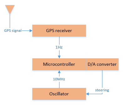
The algorithm inside the microcontroller is similar to a PLL. Edge triggers on both the signals are used to calculate the phase difference between the GPS and the oscillator and the control voltage is used to attempt to phase-align them. Once they are aligned in phase, the oscillator signal can be said to have been ‘disciplined’ by the GPS signal.
Now that we know the basic theory of how a GPSDO works I can elaborate upon my earlier statement that a GPSDO has a finite lifespan. The reason for that is due to the long-term drift of the reference oscillator due to ageing. All crystal oscillators drift from their initial frequency as they get older, even the best ones. The manufacturer will tell you in the datasheet how much per-year you can expect the device to drift.
That’s OK though isn’t it? Surely we can correct for the drift using the control voltage input. Well yes, but only up to a point. You need to check the datasheet for the oscillator that you’re using to make sure that it can be adjusted to spec over the number of years that you intend to use it.
Be careful with ebay, there are a lot of used VCOCXO units for sale on there which I suspect have been pulled from decommissioned cell-tower equipment. These older units may have been decommissioned due to the oscillator reaching end-of-life. You need to do your research.
Modern designs tend to be very good with adjustability. To give an example, the Connor Winfield DOC100V-010.0M has annual aging of 0.3ppm and an adjustment range of +/- 10ppm giving it many decades of potential use.
Powering it up
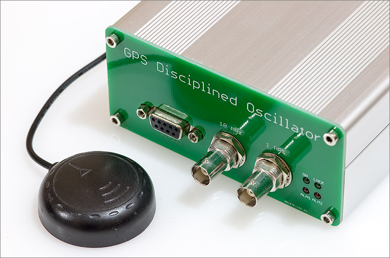
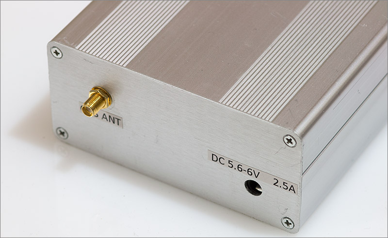
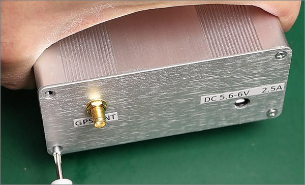
This ebay unit comes with an external 6V DC ‘wall-wart’ power supply and a GPS disc antenna on the end of a very long lead that must be more than 5 metres. That’s good because the nearest window to my desk location that has a good view of the sky is several meters away. The antenna is an active type with about 5.3V DC measured across the antenna terminal.
There are four LEDs on the front of the device. Two red ones indicate alarm conditions and the other two green ones are labelled ON and LOCK. The manual, which you can download here, tells you a bit about what to expect. When you first power up the ON and ALM1 LEDs light for a few seconds before going out. The LOCK LED will then light solid for at least an hour before the output signals become useable.
Why so long? It’s due in part to the need to wait for the OCXO to reach stable operating temperature but also because of that short-term jitter on the 1pps GPS signal that I told you about earlier. Because the jitter is random it can be averaged out over time but because you only get a new sample every second you need a lot of seconds to fully average out the jitter. My device takes about 90 minutes for the LOCK led to start flashing, indicating a useable signal but in the manual they recommend leaving it on for 24 hours for best stability. This delay is the main drawback of the GPSDO. You can’t just power up and start using it immediately.
There’s also a DB9 serial port on the front that supposedly allows us to talk to the GPS unit inside, presumably it’s just a passthrough that will allow us to send NMEA commands directly to the GPS chipset. We’ll definitely have a play with that.
The reference signals
Once the unit has decided it’s plucked enough samples from the sky to start operating then the front green LED starts flashing and a stable 10Mhz signal appears on that front-panel BNC connector. Here it is on the oscilloscope.
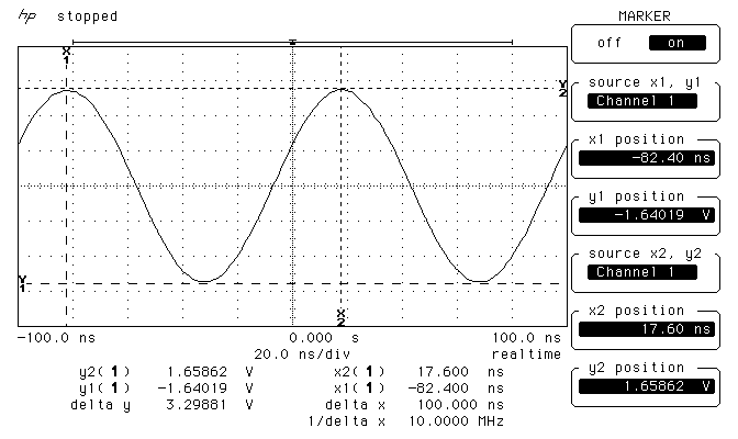
You can see that it’s a sine wave with a peak-to-peak amplitude of 3.3V. Let’s take a look at the 1pps signal as well whilst we’re here.
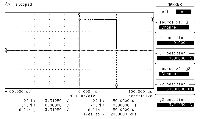
This time it’s a square wave with a duration of 50µs and an amplitude of 3.3V.
Using the 10MHz signal to calibrate a frequency counter
My Nanocounter project allows me to use an external high-accuracy 10Mhz clock as an external reference source in place of the onboard Connor Winfield TCXO. That’s very useful but I don’t always want to wait 90 minutes before I can start using the frequency counter so I also built in the ability to calibrate the TCXO using the GPSDO. In this mode the GPSDO is connected to the sample input and because the sample input is precisely 10MHz then the frequency displayed by the counter shows the error of the onboard reference oscillator.
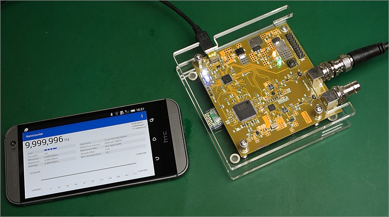
My Android firmware then stores this error offset as a calibration value and uses it to correct the readings that it gives when using the onboard oscillator as a reference. That, in a nutshell, is the reason why I had to buy a GPSDO.
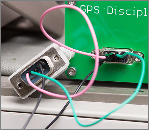
The serial port
At first it didn’t work using a ‘normal’ serial cable, exactly the same one as I use to connect an MCU UART to the PC via one of those little RS232 adapter boards that you can get on ebay. So I had a thought, maybe it needs a crossover, or null modem cable as they used to be called. I don’t have one of those cables any more so I hacked it using my existing cable and some jumper wires.
Success! it works. I was able to connect to the port using the 57600/8/N/1 settings. This is what the ‘help’ command gets you:
UCCM-P > help
*IDN?
ALARm:HARDware?
ALARm:OPERation?
DIAGnostic:OUTPut ON|OFF
OUTPut:ACTive:ENABle
OUTPut:ACTive:DISable
OUTPut:ACTive:HOLDover:DURation:THReshold <seconds>
OUTPut:ACTive:HOLDover:DURation:THReshold?
OUTPut:INACTive
OUTPut:INACTive?
OUTPut:STATe?
SYNChronization:HOLDover:DURation:STATus:THReshold <seconds>
SYSTem:PRESet
SYNChronization:TFOMerit?
LED:GPSLock?
SYNChronization:FFOMerit?
GPS:POSition N or S,<deg>,<min>,<sec>,E or W,<deg>,<min>,<sec>,<height>
GPS:POSition?
GPS:POSition:HOLD:LAST?
GPS:REFerence:ADELay <numeric value>
GPS:REFerence:ADELay?
GPS:SATellite:TRACking:COUNt?
GPS:SATellite:TRACking?
DIAGnostic:ROSCillator:EFControl:RELative?
SYNChronization:TINTerval?
DIAGnostic:LOG:READ:ALL?
DIAGnostic:LOG:CLEar
SYSTem:PON
OUTPut:MODE?
SYSTem:STATus?
SYSTem:COMMunication:SERial1:BAUD 9600|19200|38400|57600
SYSTem:COMMunication:SERial1:BAUD?
SYSTem:COMMunication:SERial1:PRESet
SYSTem:COMMunication:SERial2:BAUD 9600|19200|38400|57600
SYSTem:COMMunication:SERial2:BAUD?
SYSTem:COMMunication:SERial2:PRESet
OUTPut:STANby:THReshold <seconds>
changeSN
SYNChronization:REFerence:ENABLE LINK|GPS
SYNChronization:REFerence:DISABLE LINK|GPS
SYNChronization:REFerence:ENABLE?
STATus
POSSTATus
TOD EN|DI
TIME:STRing?
REFerence:TYPE GPS|LINK
REFerence:TYPE?
PULLINRANGE 0|1|2|...|254|255
PULLINRNAGE?
DIAGnostic:LOOP?
DIAGnostic:ROSCillator:EFControl:DATA GPS|<value>
DIAGnostic:ROSCillator:EFControl:DATA?
OUTPut:TP:SELection PP1S|PP2S
OUTPut:TP:SELection?
GPSystem:SATellite:TRACking:EMANgle <degrees>
GPSystem:SATellite:TRACking:EMANgle?
DIAGnostic:TCODe:STATus:AMASk
DIAGnostic:TCODe:STATus:OMASk
DIAGnostic:TCODe:ERRor:AMASk
DIAGnostic:TCODe:ERRor:OMASk
DIAGnostic:HOLDover:DELay
DIAGnostic:HOLDover:DELay?
GPS:SATellite:TRACking:IGNore <PRN>, ...,<PRN>
GPS:SATellite:TRACking:IGNore?
GPS:SATellite:TRACking:INCLude <PRN>, ...,<PRN>
GPS:SATellite:TRACking:INCLude?
GPS:SATellite:TRACking:<select>:ALL
Command Complete
That’s quite an impressive command set and we’re definitely not dealing with a simple passthrough to the GPS module. Let’s take a look at the output of the main status command:
UCCM-P > STATus

                 - UCCM Slot STATE -


1-1. #Now ACTIVE STATUS ---------------- [Master]
1-2. #Before ACTIVE STATUS ------------- [OCXO Warm]
2-1. #Reference Clock Operation -------- [Not Used]
2-2. #Current Reference Type ----------- [LINK]
2-3. #Current Select Reference --------- [GPS 1PPS]
2-4. #Current Reference Status --------- [Good Accuracy & Stable]
     #GPS STATUS ----------------------- [Available]
     #Priority Level ------------------- [LINK > GPS]
     #ALARM STATUS
     #H/W FAIL ---------- [ LINK ]
3-1. PLL STATUS ------------------------ [Enable]
3-2. Current: PLL MODE ----------------- [NORMAL 2 MODE]
Command Complete
The output from the status command shows that everything is in order. The unit is working with what it says is ‘Good Accuracy’.
A command is available to show the status of the GPS so let’s take a look at that.
UCCM-P > POSSTATus
-----------------------------------------------------------------------------
11/6/2016 18:20:00
-----------------------------------------------------------------------------
 Position : LAT(N 51:XX:XX.XXX) LON(E 0:XX:XX.XXX) H(27.50 m MSL)
-----------------------------------------------------------------------------
 Geometry : PDOP(0.0) HDOP(38.8) VDOP(38.8)
-----------------------------------------------------------------------------
 Channel Status
   num of visible sats > 10
   num of sats tracked > 4
   ------ Receiver Channel State ------
     CH 0 >  SateID(7) TrackMode(pos avail) SigValue(40)
     CH 1 >  SateID(9) TrackMode(pos avail) SigValue(36)
     CH 2 >  SateID(13) TrackMode(pos avail) SigValue(31)
     CH 3 >  SateID(30) TrackMode(pos avail) SigValue(33)
     CH 4 >  SateID(0) TrackMode(code search) SigValue(0)
     CH 5 >  SateID(0) TrackMode(code search) SigValue(0)
     CH 6 >  SateID(0) TrackMode(code search) SigValue(0)
     CH 7 >  SateID(0) TrackMode(code search) SigValue(0)
     CH 8 >  SateID(0) TrackMode(code search) SigValue(0)
     CH 9 >  SateID(0) TrackMode(code search) SigValue(0)
     CH 10 >  SateID(0) TrackMode(code search) SigValue(0)
     CH 11 >  SateID(0) TrackMode(code search) SigValue(0)
-----------------------------------------------------------------------------
  Rcvr Status(1) :
-----------------------------------------------------------------------------
  Antenna Voltage: 5725 mV,  Antenna Current: 22 mA
-----------------------------------------------------------------------------
Command Complete
I blanked out the GPS location
Apparently I am tracking four satellites out of a possible ten. I’ve run this command many times in a row and it does dynamically acquire and drop satellites as the signal strength changes.
Lastly, the all-important status of the timing loops:
UCCM-P > DIAGnostic:LOOP?
-------------------------------------------------------------------------------
11/6/2016 18:54:56
-------------------------------------------------------------------------------

   LOS      MEAS       NCO STATUS WEIGHT PBUC FBUC DBUC LBUC IBUC G  M TC
-------------------------------------------------------------------------------
 0:  1  0.000e+00  0.000e+00 0x07AC   0   700  700    0    0    0  2  4 29
 1:  1  0.000e+00  0.000e+00 0x068C   0   700  700    0    0    0  2 14 226
GPS: 0 -7.717e-08 -7.255e-08 0x0000   1  ---- 1000 1000 ---- ----  3  6 31
-------------------------------------------------------------------------------
freq cor  = -7.254663e-08
phase cor = -3.276800e-10
gps phase = 3.066667e-08
temp cor  = -5.801979e-11
Command Complete
I’d guess that the ‘cor’ values indicate corrections but unfortunately I can’t find a manual that would confirm that. Now that I’ve had a play with the unit I definitely had to have a look inside to see how it’s been put together.
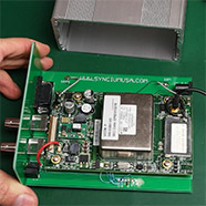
Teardown
Taking the unit apart is very straightforward. There are four philips-type screws in the back that need to be removed first.
Secondly the nut holding the antenna connector to the back panel has to be removed. An 8mm spanner is required for this, or a pair of pliers will probably do it.
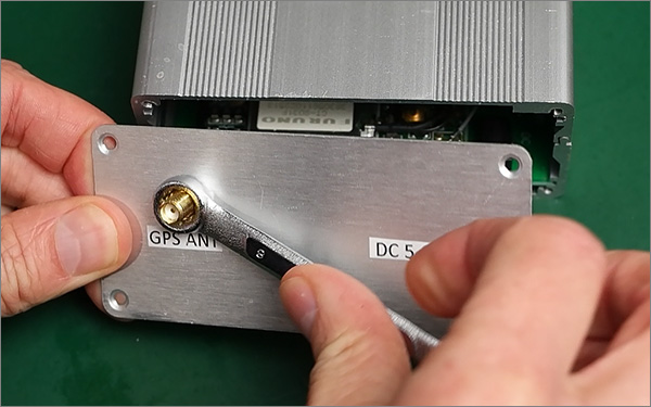
Finally the four hex screws that secure the front panel have to be removed.
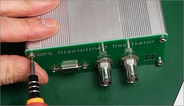
With all the screws removed you simply pull on the front panel and the whole assembly slides out the front of the extruded aluminium case. With the case removed we can see the whole unit.
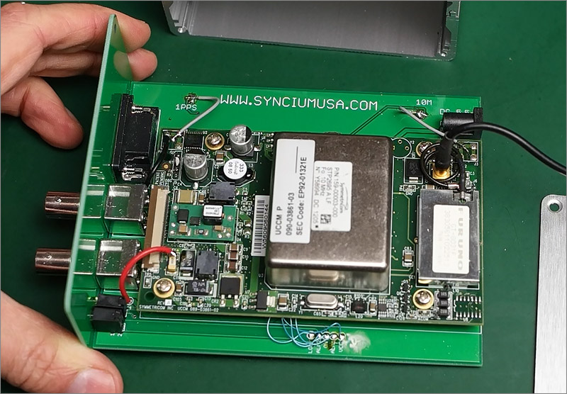
The design did actually surprise me. I was expecting to see an OCXO pulled from something else together with a modern GPS unit and an MCU to co-ordinate the synchronisation all mounted on a custom PCB. What we’ve actually got is an entire Symmetricom GPSDO pulled from some other device and mounted on to a trivial minimal PCB that does nothing more than break out connections to the front panel.
Let’s take a look at some of the parts on this.
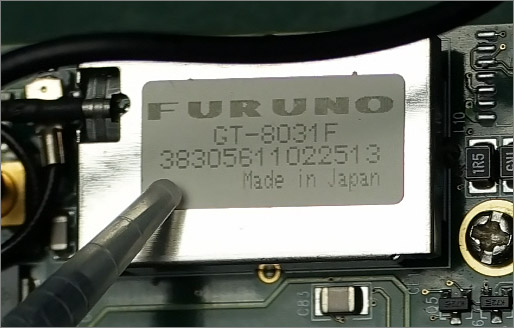
The main GPS unit is a Furuno GT-8031F that still exists as a product to this day. It’s mounted under an RF shielding can as you’d expect from a sensitive unit like this.
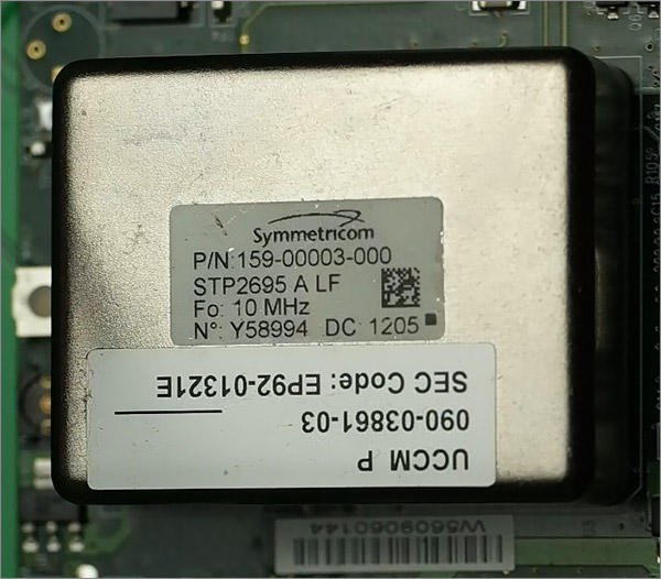
The OCXO is made by Symmetricom themselves and the part number is STP2695. The date code is visible as the 12th week of 2005 which at the time of writing is eleven years ago. STP probably stands for “Symmetricom Time Provider” and UCCM-P is a Cisco product which gives us a clue as to the original use for this board. I can’t find any information online for the STP2695 but information on a similarly numbered device, the TP2700, is available and does give us an insight into what these boards are capable of. With no information available on the aging characteristics of the OCXO I cannot know how far it might have drifted in eleven years of use.
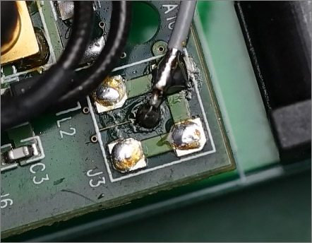
Here’s how the designers have bodged in a wire to link the 10MHz output to the front panel BNC connector. That component footprint is immediately recognisable to me as that of a mini SMA connector. The designers have desoldered it and bodged in a wire connected to the center signal pin and stripped back the insulation far enough to be able to solder down the ground shield to one of the corner pads. Ugly, very ugly. If there are any time-nuts out there reading this I’d be interested to know what impact this kind of bodge has on the integrity of the signal. If it’s detrimental to the performance of the unit then I may well get in there and replace the surface mount SMA connector and provide a quality link to the front panel BNC connectors.
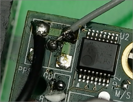
And here’s a similar bodge for the 1pps output only this time for good measure there’s a second bodge wire that leads to the shield connections for the front panel BNC connectors. No attempt to clean up the mess made by the rework has been made. I couldn’t identify the IC on the right from its ID number but the only traces coming from it lead to the serial connector indicating that it’s probably an RS232 driver. The black smudge on the surface is heat damage from whatever tool they used to remove the SMA connector, probably a hot air gun.
Video
I made a video that shows the general operation of this GPSDO as well as the complete teardown. The video has a more complete view of the teardown and shows even more bodges hiding underneath the main board. You can watch it here in the web page but for the best full HD view you should watch it directly on the YouTube website.
Final words
I hope you’ve enjoyed this review and teardown as much as I have doing it for you. I’m happy that I’ve got a unit that’s based on something of very high quality even if the ‘aftermarket’ modifications made to it are of a low quality.
Feel free to leave a comment below, or if you’d like to start a discussion then click here to visit the forum thread.