


Directly driving a 7-segment LED display with the STM32
Seven segment LEDs are an extremely cost effective way to add a large, bright and very readable numeric display to your project.
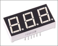
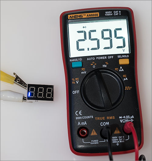
Displays similar to the one pictured above can be had for as little as 50 cents each on ebay in the common heights of 0.56″, 0.36″ and 0.28″. You can choose anywhere between one and four digits in the same package. They’re referred to as seven segment but really they’re eight because each digit comes with a little decimal point down at the bottom right.
Configuration
The multiple digit packages utilise a wiring configuration designed to minimise the number of pins required to drive it without having to embed any logic at all within the package.
If you count the number of segments on, for example, a three digit display you’d quickly realise that a simple configuration that exposed each LED on its own dedicated pin would require (8 * 3) + 1 = 25 pins on the package, of which you would need to attach 24 to your MCU to drive it. That’s far too many and is the reason why they come in common cathode or common anode configurations.
Common cathode configuration
Let’s look at common cathode first.
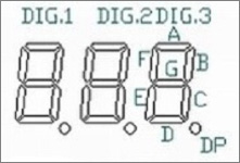
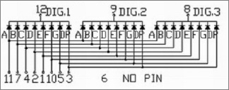
In this configuration there are dedicated power pins for each of the 7 segments but the same segment on each digit are all connected together. On the other side of the LED you can see that all eight cathodes for a digit are tied together and presented at a single pin.
If you take a moment to digest this you can see how we can light up a segment of our choosing on any digit. For example, to light up segment A on digit two we would apply a current to pin 11 while grounding pin 9. Pins 8 and 12 must be disconnected or otherwise prevented from allowing current flow.
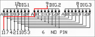
To light segment A on digit 1 we would disconnect pin 9 and ground pin 12, and finally for digit 3 we would disconnect pin 12 and ground pin 8.
Multiplexing
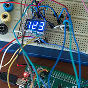
Now you should be getting an idea of how these displays are intended to be driven. Let’s look at a fully worked example of how we would display the number “123”.
Firstly we would light segments E, F on digit 1 by enabling current flow through pins 1, 10 and 12. Then we would light segments A, B, D, E, G on digit 2 by enabling pins 11, 7, 2, 1, 5 and 9. Finally we would light segments A, B, C, D, G by enabling only pins 11, 7, 4, 2, 5 and 8.
If we repeat the above actions fast enough then the human eye will perceive all three digits to be constantly lit even though we are switching them on and off very quickly.
Common anode configuration
This article is going to focus on the common cathode type of display but for completeness I’ll show you the other configuration, just so you know that two incompatible types are available.
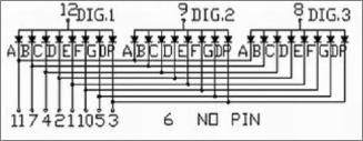
In the common anode configuration we again have separate pins for each segment and again all equal segments on all digits are wired together but this time the cathode ends of the segment LEDs are individually exposed and it’s the anodes that are all connected together on each digit.
The multiplexed driving technique is exactly the same for common anode displays but that doesn’t mean you could use common anode where a design calls for common cathode because you can’t, you would have to change the design.
Driving with an MCU
There are a few options available if you have an MCU and you want to drive one of these displays. If you have an MCU with a limited number of IO pins, such as an Arduino Uno then your best option is to use a dedicated driver IC that will do the work for you.
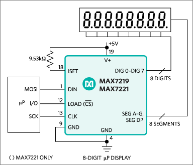
The Maxim MAX7221 will drive common cathode displays of up to a whopping eight digits while requiring just a three wire SPI interface to the host MCU. Using just one of these ICs you could have two of the biggest four digit displays in your project at a cost of just three MCU pins. I’ve used this IC many times before in projects that you can read about on this site. The main drawback of this IC is that it requires a 5V supply and 5V levels at the SPI pins. This is no problem for the Arduino Uno but it means it can’t be used with an STM32 without a level shifter.
If you’re using an MCU with a large number of GPIOs, such as most of the STM32 packages, then you have the option of driving these displays directly for the cost of just eight resistors and three n-channel MOSFETs, and that’s the method that we’re going to explore here today.
Direct drive circuit
Here’s the circuit diagram that I use to drive a three digit display that has blue LEDs. It’s a snapshot from a much larger circuit that I’m working on.
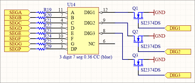
The choice of resistor is important because it limits the amount of current flow and sets the overall brightness of the display. I’ll be using the STM32 F0 discovery board that hosts an STM32F051 MCU to implement this circuit.
The first thing that I need to do is find the MCU datasheet and determine the maximum current that the device can source and sink.
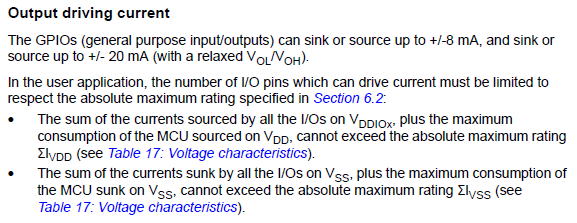
Those limits make reference to another table earlier in the datasheet that tells us the total current source and sink for all pins.
So we have a per-pin absolute limit of 20mA and an overall device limit of 120mA. To avoid heat buildup and allow the device to actually do other work as well we will stay far away from those limits.
Are there any other limits? Yes there are. It pays to read the entire datasheet because hidden away in a footnote there is a very important limitation regarding GPIOs PC13 to PC15.

We will not use these pins.
Resistor calculation
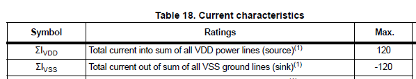
To calculate the resistor values we need to know the forward voltage of the LEDs in the display. This is easily tested by using your multimeter in its diode testing mode.
The meter shows a forward voltage of about 2.6V which is average for a blue LED. Now I’ll take a wild guess that because modern LEDs are very bright at low currents then 2mA will be sufficient current to get a nice, readable brightness. To match the STM32 F0 Discovery board I’ll test this with a 3.0V supply. That means a resistor of (3.0 – 2.6) / 0.002 = 200Ω is required.
LEDs don’t photograph well so please take my word for it that this is nice and bright. Can the STM32 handle it? 2mA falls well below the per-pin limit and the worst case scenario is going to be all eight segments lit at the same time giving a total current source of 8 * 2 = 16mA. No problem at all. The package shouldn’t even get warm.
The problem with using the 200Ω resistor that we calculated is that each digit is only lit for 33% of the time which will make it appear three times as dim as we are expecting. Therefore we need to lower the resistor by a factor of 3 and use a value of 68Ω instead.
This will raise the peak current seen by the LED to 6mA but the average current will still be 2mA. In the worst-case scenario where your MCU hangs or crashes while driving all eight segments of a digit then it will be sourcing 8 * 6mA = 48mA. This is still within safe levels and will not burn up the package.
This figure of 48mA is the reason for each digit pin being switched on or off using a MOSFET. If we were to directly connect these pins to the MCU then we would be in danger of sinking 48mA into a single pin which would probably permanently damage it.
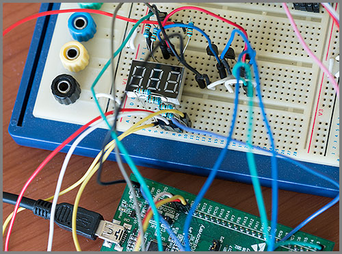
The resistors, MOSFETs and jumper wires are all in place and we are ready to develop the firmware. My project circuit specifies the Vishay SI2374DS MOSFET which is a surface mount device. For this test I am using the through-hole BS170 instead. The choice of n-channel MOSFET is not important but for efficiencies sake you should choose one with a low on-state drain-to-source resistance. Less than 1Ω is easily found.
Firmware
I chose to implement the firmware as an example project within my stm32plus library. The concepts are simple so you should have no issues porting it to whatever framework suits your project. The firmware is implemented in a single file that you can view here on Github.
The design works by using Timer 1 to generate interrupts at a frequency of 180Hz. Each time the interrupt fires we turn off the digit that we were last displaying and move on to setting the GPIOs necessary to light the next digit. Therefore each digit flickers rapidly at 180/3 = 60Hz, a figure I selected to match the refresh rate most commonly used by PC monitors. This gives a display that appears stable to the human eye.
Here’s a breakdown of the important parts of the firmware.
static const uint8_t AsciiTable[]= {
  0,  // SPACE
  0,0,0,0,0,0,0,0,0,0,0,0,0,0,0,  // skip
  0b11111100,  // 0
  0b01100000,  // 1
  0b11011010,  // 2
  0b11110010,  // 3
  0b01100110,  // 4
  0b10110110,  // 5
  0b10111110,  // 6
  0b11100000,  // 7
  0b11111110,  // 8
  0b11110110   // 9
};
We want to allow the controller to display ASCII text strings so we need a table to convert ASCII to a bitmap of which segments should light up for that character. Printable ASCII starts at 32 (space) so we start our table there.
Each entry in the table is a single byte with one bit per lit-up segment in the format ABCDEFG0. Unused ASCII codes are set to zero. In this example I only need the digits 0-9 so that’s all there is in there. You can easily see how to extend this.
enum {
  SEGA = 0,   // PA0
  SEGB = 3,   // PA3
  SEGC = 8,   // PB8
  SEGD = 4,   // PB4
  SEGE = 3,   // PB3
  SEGF = 1,   // PA1
  SEGG = 2,   // PA2
  SEGP = 5,   // PB5
  DIG1 = 9,   // PB9
  DIG2 = 2,   // PB2
  DIG3 = 10   // PB10
};
The pins used for each GPIO are stored in an enum for easy reference. The seemingly random assignment matches a project I’m currently working on and also shows that the pin placement is completely flexible.
GpioA<DefaultDigitalOutputFeature<SEGA,SEGB,SEGF,SEGG>> pa;
GpioB<DefaultDigitalOutputFeature<DIG1,DIG2,DIG3,SEGC,SEGD,SEGE,SEGP>> pb;
All pins are initialised as outputs. To light a segment I will set the segment output and the corresponding digit MOSFET gate output HIGH. Current will flow from the segment output GPIO, through the LED and the MOSFET and the LED will light. To switch a digit off I simply switch off its MOSFET.
/*
 * Initialise timer1 running from the high speed internal APB2 (APB on the F0)
 * clock with an interrupt feature
 */

Timer1<
  Timer1InternalClockFeature,       // the timer clock source is APB2 (APB on the F0)
  Timer1InterruptFeature            // gain access to interrupt functionality
> timer;

/*
 * Set ourselves up as a subscriber for interrupts raised by the timer class.
 */

timer.TimerInterruptEventSender.insertSubscriber(
    TimerInterruptEventSourceSlot::bind(this,&Timer7SegmentTest::onInterrupt)
  );


/*
 * Set an up-down-timer up to tick at 80kHz with an auto-reload value of 444
 * The timer will count from 0 to 444 inclusive, raise an Update interrupt and
 * then go backwards back down to 0 where it'll raise another Update interrupt
 * and start again. Each journey from one end to the other takes 1/180 second.
 */

timer.setTimeBaseByFrequency(80000,444,TIM_CounterMode_CenterAligned3);

/*
 * Enable just the Update interrupt, clearing any spurious pending flag first
 */

timer.clearPendingInterruptsFlag(TIM_IT_Update);
timer.enableInterrupts(TIM_IT_Update);

/*
 * Start the timer
 */

timer.enablePeripheral();
Setting up the timer in stm32plus is a simple task of declaring it with the clock and interrupt feature, inserting ourselves as a subscriber to the interrupts, setting the desired frequency and then enabling the peripheral.
int value = -1;

for(;;) {

  value++;

  if(value>999)
    value = 0;

  // translate value to ascii, left justified

  _display[0]=_display[1]=_display[2]=0;
  StringUtil::itoa(value, const_cast<char *>( _display), 10);

  // wait for 100ms

  MillisecondTimer::delay(100);
}
The example code then goes into an infinite loop counting up from zero to 999 and then wrapping around and starting again.
/*
 * Subscriber callback function. This is called when the update interrupt that we've
 * enabled is fired.
 */

void onInterrupt(TimerEventType tet,uint8_t /* timerNumber */) {

  // verify our expectation

  if(tet!=TimerEventType::EVENT_UPDATE)
    return;

  // turn off the last digit we displayed. This needs to be done first to avoid
  // switched off segments becoming faintly visible during multiplexing

  _digits[_currentDigit].reset();

  // advance to the digit we just set up

  if(_currentDigit>=2) {
    _currentDigit=0;
    _currentDigitPtr=_display;
  }
  else
    _currentDigit++;

  // get the character to display at this position

  uint8_t c=*_currentDigitPtr++;

  // check the bottom end of the range

  if(c<=' ')
    c=' ';

  // get the segment state bitmap from the table

  uint8_t bits=AsciiTable[c-' '];

  // for each bit in the map, set/reset the correct state in the segments

  for(uint8_t j=0;j<7;j++) {
    bool state=(bits & 0x80)!=0;
    _segments[j].setState(state);
    bits <<= 1;
  }

  // process the decimal point if there is one

  if(*_currentDigitPtr=='.') {
    _segments[7].set();
    _currentDigitPtr++;
  }
  else
    _segments[7].reset();

  // switch on the digit we have set up

  _digits[_currentDigit].set();

  // we'll be back in 1/180s which means we are displaying each digit at 60Hz
}
This is the interrupt handler where the real work happens. We switch off the previous digit before setting up the seven segments that form the next digit. We then explicitly check to see if we need to turn on the decimal point before finally lighting up the next digit.
You’ll need to view the entire file to see the types of the member variables that are used but you should be able to understand the logic flow from this snippet.
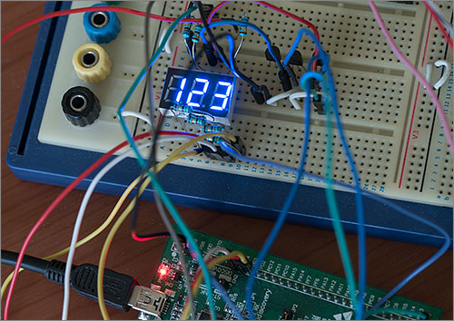
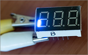
Here’s a photograph of the display in action. It works as expected and the display is a comfortable and even brightness with no artifacts or flickering observed.
Adapting this technique for your project
If you want to use this technique in your own project then you should follow the same procedure that I did. To summarise:
- Count up the pins you’ll need and verify you have enough available on your MCU.
- Measure the forward voltage of your LED segments and experiment to find a low current level that gives a usable brightness.
- Calculate a resistor that limits the LED current to your selected value and then divide it by the number of digits on your display.
- Verify that your MCU can source the current you will draw, taking into account the worst case scenario where the MCU hangs and a digit is permanently on with all segments lit.
- Select an n-channel MOSFET with a low drain-source resistance (less than 1Ω is easily achievable) and check that the on-state power dissipation is well below the maximum the package can support.
If you need any help with driving these displays then please feel free to contact me or leave a message down below in the comments.