Tags
Related Posts
Share This


Project Difficulty
- All components are commonly available.
- The smallest IC pin pitch is 0.5mm
- The 0402 TVS diodes are not required
- The smallest discrete component is 0603.
- All components are on the top-side of the board
Recent Posts
Process automation: another RTD sensor board
In a previous article I described the design and build of a temperature sensor board based around a high precision LTC2986 part from Linear Technology. The project was successful so you may be wondering why I’m bothering to design another board when the LTC2986 probably cannot be bettered by any other fully integrated part on the market.
Well, I have no clear answer except that with a pile of left over parts from the LTC2986 board BOM and seeing that the Maxim MAX31865 RTD-to-digital converter is quite cheap compared to the LTC2986 then why not? I could always justify it to myself by calling it a backup unit in case something goes awry with the board I’ve already built.
So without further ado and before I talk myself out of it, let’s get on with the design.
The MAX31865
The MAX31865 is a single-sensor, fully integrated resistance-to-digital converter requiring very few external parts to operate. This is the block diagram taken from the datasheet.
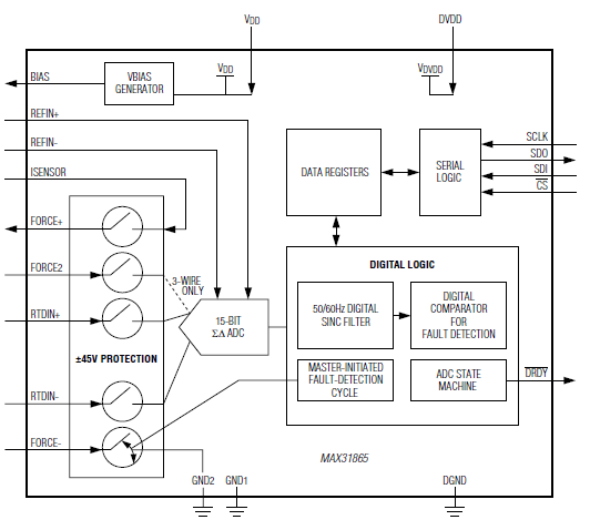
Once the usual supply decoupling capacitors are accounted for the only other part that’s required is a precision reference resistor which, for PT100 sensors is recommended to be 400Ω. More good news for hobbyists is that the communication interface is SPI and the final pin count is low enough for Maxim to be able to offer it in an easy-to-handle SSOP package.
Now I’ll move on to building a schematic around this part.
Schematic
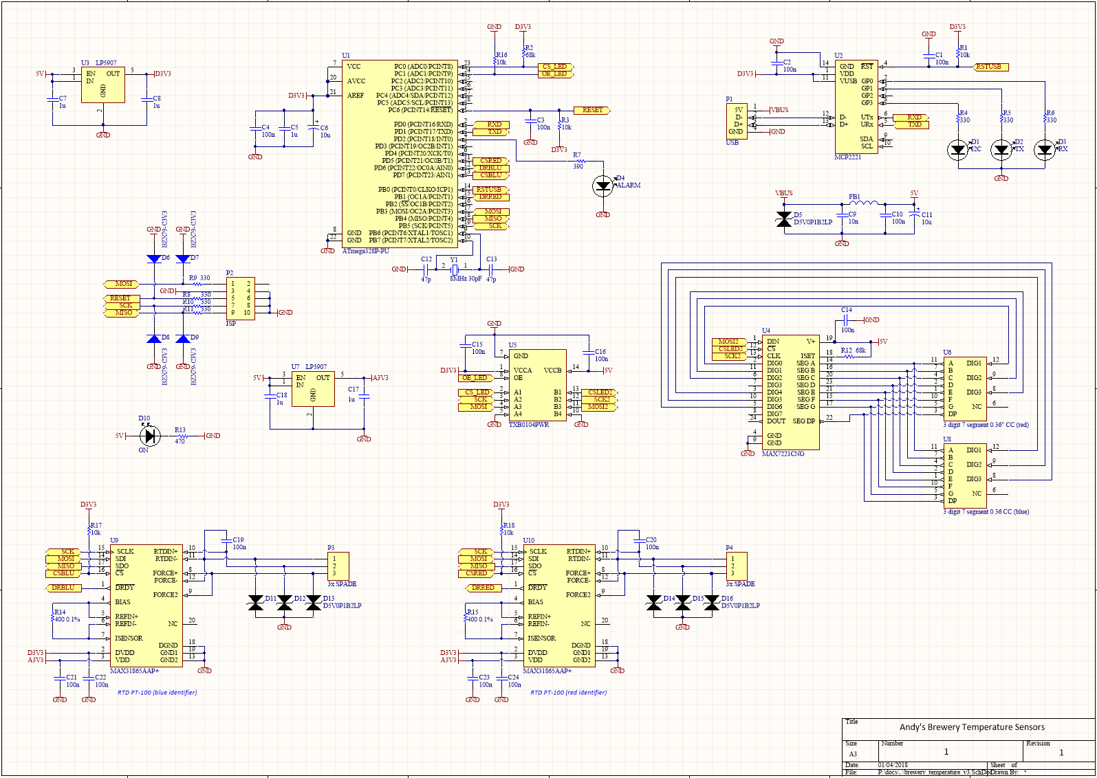
Click on the thumbail for a much larger version
In order to make this design operationally as close as possible to my LTC2986 design I will include two MAX31865 ICs on this board (the LTC2986 can control two three-wire sensors on a single chip). Let’s take a look at the details.
Power supplies
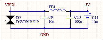
It all starts with the USB input from the computer. I add an ESD diode to the 5V line and then filter it through a combination of capacitors and a ferrite bead. I wrote an article on this approach to filtering the USB supply a while ago, click here to read it.
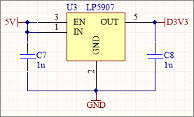
The MAX31865 is a 3V3 part with separate power inputs for the digital and analogue parts. A cheap design could just tie these two inputs together and live with possibility of digital switching noise interfering with the ADC but it doesn’t cost much to do this properly and I have a few Texas Instruments LP5907 ultra-low noise regulators in stock so I’ve used a pair of them here, one each for the digital and analogue supplies.
The sensor controller
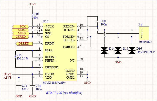
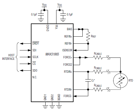
Nothing radical here, the MAX31865 doesn’t need much in the way of supporting parts. The 400Ω reference resistor is a 0.1% part and the MAX31865 datasheet tells you how to wire up the various RTDIN and FORCE pins for a three-wire probe.
I’ve attached optional ESD protection diodes on the RTD pins as these are circuits that are likely to be touched by humans with their annoying tendancy to harbour a static charge. I say optional because all the IC pins come with integrated ±2kV ESD protection anyway and these ESD diodes tend to come in horrible tiny packages that disintegrate at the slightest provocation.
The MCU
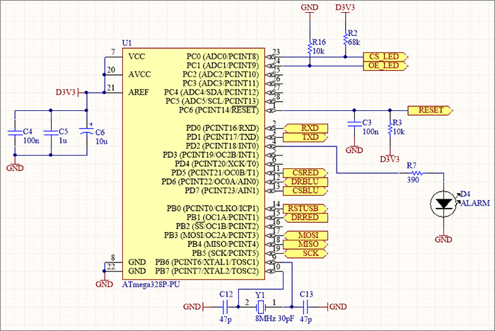
It’s the venerable ATmega328p, simply because that’s the one I used on the LTC2986 design, I have a few left and much of the firmware will be reusable saving me considerable time and effort. I’ll run the MCU at 8MHz which is plenty fast enough for this design.
The onboard 7-segment LEDs
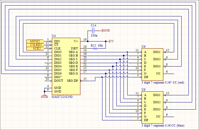
The trusty MAX7221 makes another appearance here. It’s so easy to control and requires only one external resistor to set the LED current. The only annoyance with it is that it’s a 5V device and the logic inputs have a VIH minimum level of 3.5V. That means I need a level translator to hook it up to the MCU.
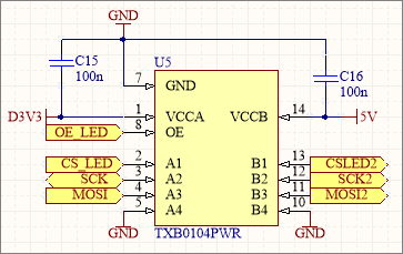
Step-up translators are not as common as step-down, but the Texas Instruments TXB0104 does the job for up to four signals and is easily integrated between the MCU and the MAX7221.
The USB-to-serial interface
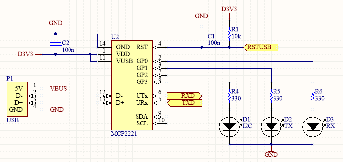
The usual Microchip MCP2221 that I’ve been using in the last couple of designs makes an appearance here. It’s a trivial to use plug-and-play chip that comes in a nice convenient DIP package. The rumour on the internet is that this is actually a hardwired PIC.
The ISP interface
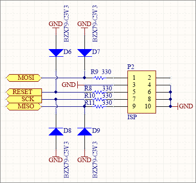
I program these ATmega devices using the popular USBASP programmer that you can get on ebay for just a few pounds and I’ve got one that has a jumper on it for selecting 3.3V or 5V.
For years I’d just assumed that this jumper switched the supply to the onboard ATmega8A so that the whole system would run at 5V or 3.3V.
It doesn’t.
It only switches ISP output pin 2 (Vcc). All the SPI pins and the RESET pin remain at 5V whatever the jumper is set to and for 3.3V circuits where multiple devices are connected to the SPI bus this may cause a problem because the other devices may not be tolerant to the 5V levels that they’re going to be hit with during MCU programming.
To be safe I’ve opted to use cheap zener diodes and resistors to cap the levels on the ISP bus to near-enough 3.3V. This works for the slow speed of the programming bus but wouldn’t work at high speeds so it’s not a cookie-cut approach that you can take and apply everywhere. I’ve also disconnected pin 2 because the board will be powered from the USB bus and not from the USBASP programmer.
Bill of materials
Here’s a complete bill of materials for this design. Where possible I’ve included a sample Farnell order code to make it easy to search for parts. In my case I actually put the parts together for this BOM from Digikey UK because they have the MAX31865 in SSOP format and the 400Ω precision resistor.
| Designator | Value | Quantity | Description | Footprint | Farnell code | Note |
|---|---|---|---|---|---|---|
| C1, C2, C3, C4, C10, C14 | 100n | 6 | Ceramic capacitor | 2.54mm | 2309020 | |
| C5 | 1µ | 1 | Ceramic capacitor | 5.08mm | 2112910 | [1] |
| C6, C11 | 10µ | 2 | Electrolytic capacitor | 5x11mm | 1902913 | |
| C7, C8, C17, C18 | 1µ | 4 | Ceramic capacitor | 0603 | 9227776 | |
| C9 | 10n | 1 | Capacitor | 2.54mm | 2309024 | |
| C12, C13 | 47p | 2 | Capacitor | 2.54mm | 2395776 | |
| C15, C16, C19, C20, C21, C22, C23, C24 | 100n | 8 | Capacitor | 0603 | 1759037 | |
| D1, D2, D3 | Amber | 3 | LED | 3mm | [2] | |
| D4 | Red | 1 | LED | 3mm | [2] | |
| D5, D11, D12, D13, D14, D15, D16 | D5V0P1B2LP-7B | 7 | Bi Directional TVS Diode | 0402 | [6] | |
| D6, D7, D8, D9 | BZX79-C3V3 | 4 | Zener Diode | AXIAL-0.3 | 1097229 | |
| D10 | Green | 1 | LED | 3mm | [2] | |
| FB1 | BLM18PG221SN1D | 1 | Ferrite bead | AXIAL-0.3 | 2292304 | |
| P1 | USB B | 1 | USB B RECEPTACLE | 1177885 | ||
| P2 | 2x5 header | 1 | ISP connector | 2.54mm | [3] | |
| R1, R3, R16, R17, R18 | 10k | 5 | Resistor | AXIAL-0.3 | 2329609 | |
| R2, R12 | 68k | 1 | Resistor | AXIAL-0.3 | 2329546 | |
| R4, R5, R6, R8, R9, R10, R11 | 330 | 7 | Resistor | AXIAL-0.3 | 2329514 | |
| R7 | 390 | 1 | Resistor | AXIAL-0.3 | 2329519 | |
| R13 | 470 | 1 | Resistor | AXIAL-0.3 | 2329531 | |
| R14, R15 | 400 0.1% | 2 | Resistor | 0603 | ||
| U1 | ATMega328P | 1 | 8-bit AVR Microcontroller | DIP-28 | 1715487 | |
| U2 | MCP2221-I/P | 1 | Microchip USB-Serial | DIP-14 | 2434892 | |
| U3, U7 | LP5907-3.3 | 2 | TI voltage regulator | SOT23-5AM | 2492304 | |
| U4 | MAX7221CNG | 1 | LED Display Driver | DIP-24 | [4] | |
| U5 | TXB0104PWR | 1 | Level converter | TSSOP14 | 1607891 | |
| U6 | 1 | red 3 digit 7 segment 0.36" LED | custom | [5] | ||
| U8 | 1 | blue 3 digit 7 segment 0.36" LED | custom | [5] | ||
| U9, U10 | MAX31865AAP+ | 2 | Maxim resistance to digital converter | SSOP20 | [7] | |
| Y1 | 1 | Crystal Oscillator - 8MHz 30pF | HC49 thru hole | 2063945 |
- 2.54mm parts can also be used if you carefully bend the leads outwards to fit the wider 5.08mm pitch.
- Any colour of 3mm LED will work and they’re cheapest on ebay.
- These 2.54mm headers are cheapest on ebay.
- The MAX7221 seems to be cheapest on Ali Express.
- Make sure you get the 0.36″ common-cathode variety. The red ones are easy enough to find but the blue ones are more elusive. I got mine from Ali Express. Search for item #32789229519.
- The TVS diodes are optional and the design will work safely without them due to the built-in ESD protection on the MAX31865. These 0402 parts are hard to work with due to the fragile package and the small pads that are completely underneath the package body.
- The SSOP package is available from Digikey.
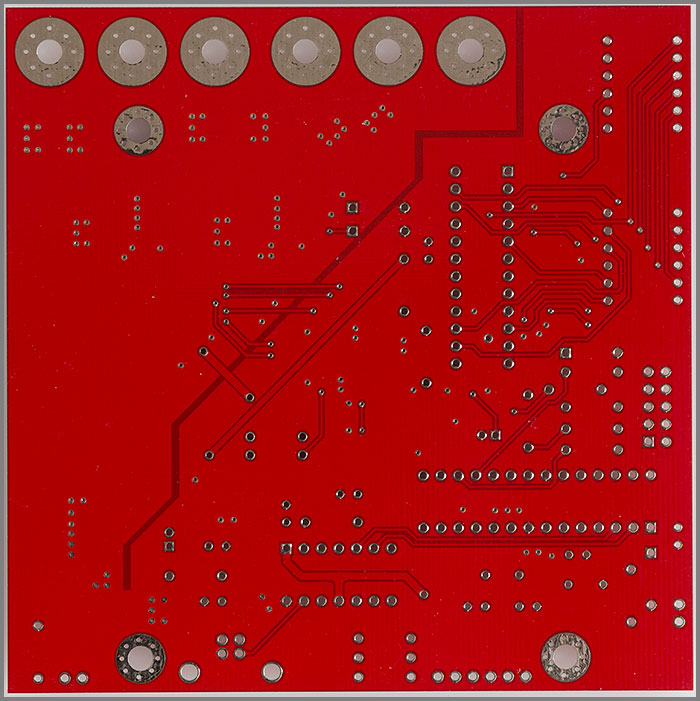
PCB layout
This layout is totally copied from the previous LTC2986 design. The digital side is more or less identical and required only a few changes. The major change is, of course, on the analogue side where the MAX31865s are located and the good news for me is that it’s considerably simpler even though there are two ICs instead of one.
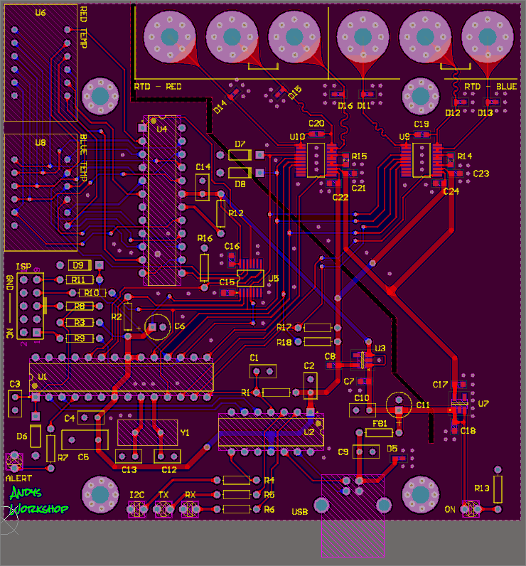
The mounting holes are of course in the same place as before as this 10x10cm PCB is designed to mount on to a 3.5″ hard disk bay.
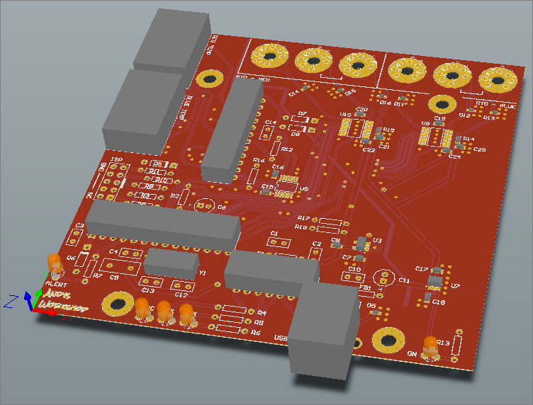
With the design laid out I previewed it in 3D to make sure that there were no silly errors such as silkscreen overlapping pads, components too close to the edge or to each other and other such gotchas. It all looked good so I sent it off to be manufactured. The Gerbers for this project are freely available if you’d like to get your own copies printed at one of the cheap fabrication houses.
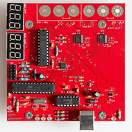
The manufactured PCBs
This time, and for no particular reason, I used Seeed Studio for the manufacturing as these 2-layer boards don’t have anything on them that tax the manufacturing tolerances. It cost about US$5 for 10 copies before shipping. Crazy prices and I’m looking forward to the day that they start discounting 4-layer boards.
I sent off my order and waited. A healthy dose of patience is a requirement when using China Post for shipping. They always quote 2 or 3 weeks for shipping and I’ve heard anecdotally that the way this works is that there is a shipping container at the major Chinese ports destined for each foreign port. Over time it steadily fills up and when it’s full off it goes on the next ship. If you’re dead lucky yours will be the last parcel on board and your parcel will arrive in a week. At the other end of the scale if your parcel is first into an empty container then you may be waiting for some time. About two weeks later my boards turned up which is neither fast nor slow, just average.
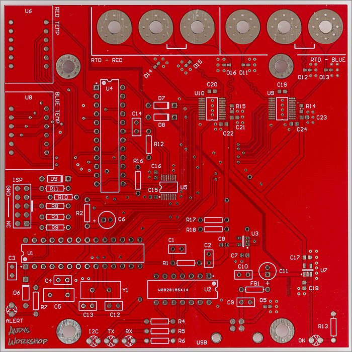
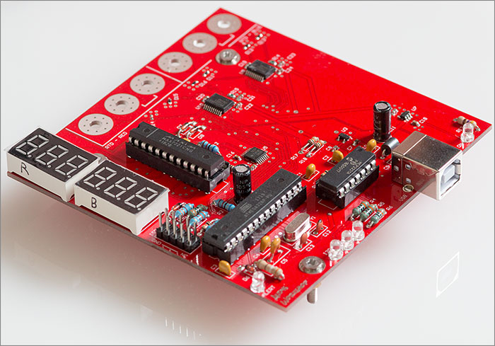
They’re all looking good, which is entirely unsurprising because this is not a difficult design to manufacture. It’s time to get assembling.
Assembly
Assembly is a two stage process because this board has both SMD and through-hole parts. The first step for me is to tin the SMD pads, apply a tacky flux and then use it to hold the parts in place on top of the little solder bumps. Then I take the board and reflow it in my android-controlled reflow oven.
After the reflow I place the board under my microscope for inspection and touch up any parts that look like they didn’t reflow properly. On this board everything that reflowed did so correctly; the only issue was that two of the 0603 capacitors got blown across the board by the fan in the reflow oven before they could reflow. These parts were easily put back in their place with my hot air gun.
After washing the board to get rid of flux residue I sat down and soldered in all the through-hole parts with my soldering iron. I opted to use sockets for my ICs as I always do because removing a through-hole IC that you suspect to be damaged is no fun whatsoever if it’s been soldered directly to the board.
There it is, ready for testing, but first just for fun let’s see it next to the LTC2986 design.
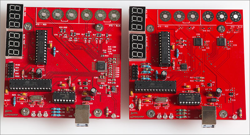
Now you can see how physically similar these boards are. It’ll be easy for me to switch them in and out as needed.
The firmware
Writing the firmware took less than two days of effort because I could lift-and-shift the LTC2986 code almost in its entirety. All I had to do was take out all the LT interface code and replace it with an equivalent that controlled the MAX31865.
You can see where some of the cost savings have been achieved with the MAX31865 vs. the LTC2986 when you come to write the interface code. The LTC2986 is hugely configurable and also directly outputs a temperature in Celsius which hints at quite a powerful core inside.
By contrast the MAX31865 has very limited configurability and outputs raw data from the ADC so you need to do the conversion to Celsius yourself. I decided to use the tried-and-trusted open source conversion implementation from Adafruit. You can see it here on Github.
The Adafruit implementation is targeted at the Arduino so I had to make a few tweaks to get it to work in this standalone firmware but nothing too serious and it was up and running in a matter of hours. My firmware is available on Github and you can view it here.
Building the firmware
As usual I use the scons system to build my firmware. It’s as simple as this:
$ scons
scons: Reading SConscript files ...
scons: done reading SConscript files.
scons: Building targets ...
avr-g++ -o AlarmFlasher.o -c -mmcu=atmega328p -Os -g -DF_CPU=8000000 -DBOARD_SERIAL=1027957644 -std=c++1y -Wall -Werror -Wextra -pedantic-errors -fno-rtti -mcall-prologues -ffunction-sections -fdata-sections -fno-exceptions AlarmFlasher.cpp
avr-g++ -o Max7221.o -c -mmcu=atmega328p -Os -g -DF_CPU=8000000 -DBOARD_SERIAL=1027957644 -std=c++1y -Wall -Werror -Wextra -pedantic-errors -fno-rtti -mcall-prologues -ffunction-sections -fdata-sections -fno-exceptions Max7221.cpp
avr-g++ -o MillisecondTimer.o -c -mmcu=atmega328p -Os -g -DF_CPU=8000000 -DBOARD_SERIAL=1027957644 -std=c++1y -Wall -Werror -Wextra -pedantic-errors -fno-rtti -mcall-prologues -ffunction-sections -fdata-sections -fno-exceptions MillisecondTimer.cpp
avr-g++ -o ProgStrings.o -c -mmcu=atmega328p -Os -g -DF_CPU=8000000 -DBOARD_SERIAL=1027957644 -std=c++1y -Wall -Werror -Wextra -pedantic-errors -fno-rtti -mcall-prologues -ffunction-sections -fdata-sections -fno-exceptions ProgStrings.cpp
avr-g++ -o Program.o -c -mmcu=atmega328p -Os -g -DF_CPU=8000000 -DBOARD_SERIAL=1027957644 -std=c++1y -Wall -Werror -Wextra -pedantic-errors -fno-rtti -mcall-prologues -ffunction-sections -fdata-sections -fno-exceptions Program.cpp
avr-g++ -o Uart.o -c -mmcu=atmega328p -Os -g -DF_CPU=8000000 -DBOARD_SERIAL=1027957644 -std=c++1y -Wall -Werror -Wextra -pedantic-errors -fno-rtti -mcall-prologues -ffunction-sections -fdata-sections -fno-exceptions Uart.cpp
avr-g++ -o brewery-max31865-rtd-v1.elf -Wl,-Map,brewery-max31865-rtd-v1.map -mrelax -Wl,-u,vfprintf -lprintf_flt -lm -Wl,--gc-sections -mmcu=atmega328p AlarmFlasher.o Max7221.o MillisecondTimer.o ProgStrings.o Program.o Uart.o
avr-objcopy -j .text -j .data -O ihex brewery-max31865-rtd-v1.elf brewery-max31865-rtd-v1.hex
Install file: "brewery-max31865-rtd-v1.hex" as "bin/brewery-max31865-rtd-v1.hex"
avr-objdump -S brewery-max31865-rtd-v1.elf > brewery-max31865-rtd-v1.lst
avr-size brewery-max31865-rtd-v1.elf | tee brewery-max31865-rtd-v1.siz
   text    data     bss     dec     hex filename
   9958     230     126   10314    284a brewery-max31865-rtd-v1.elf
scons: done building targets.
I’m currently using avr-gcc 7.2.0 but I’ve also tested it works with versions as early as 4.9.2. The newer versions do seem to be a bit more efficient on code generation, not that it matters when I’m only using 10Kb of the available 32Kb on this MCU.
When I’ve got the USBASP connected I can use scons upload to build and upload in one step and when I first connect up a fresh ATmega328p then I must use scons fuse to set the fuses to run the board at 8MHz using an external crystal.
Power supply noise rejection
The MAX31865 has built-in noise rejection filters tuned to a selectable 50 or 60Hz, the idea being that you choose one based on the mains frequency of your location. Since this is a set-and-forget option I chose to compile it in to the firmware instead of having it selectable as a command.
Here in the United Kingdom our mains frequency is 50Hz so if you’re building this firmware and you live in a country that has a 60Hz mains supply then you will need to edit Max31865.h and change the FILT50HZ value shown below to FILT60HZ.
template<class TGpioCS, class TGpioDRDY>
inline void Max31865<TGpioCS, TGpioDRDY>::setup() {

  writeByte(Register::CONFIG, ConfigBits::WIRE3 | ConfigBits::FILT50HZ);
  clearFault();
}
Testing the firmware
To test the firmware I need a serial terminal emulator. When on Windows I use the free Realterm program and when on Linux I’ll use the miniterm utility that comes with the PySerial Python package. I find Linux more convenient for working with serial peripherals and command-line based code in general so I fired up one of my Ubuntu Server virtual machines and got started. If you’re still working in a world where you only have a single operating system on your computer then I seriously recommend you try installing a VM or two. It’s liberating.
I’ve used the Linux udev system to create an alias to the /dev/ttyACM0 USB-to-serial device so that non-root users can access it. You can read a bit more about how I set that up in this article.
$ python -m serial.tools.miniterm /dev/Andy0
--- Miniterm on /dev/Andy0  9600,8,N,1 ---
--- Quit: Ctrl+] | Menu: Ctrl+T | Help: Ctrl+T followed by Ctrl+H ---
32565:"Andy's Workshop Brewery MAX31865 RTD temperature sensors"
That’s the ID command that shows it’s alive and well. The integer prefix to the command response is a CRC16 checksum of all the characters following the colon and not including the CRLF at the end. Now I know that the board is healthy I’ll switch to using the custom sendcommand utility that you can find with the firmware on Github.
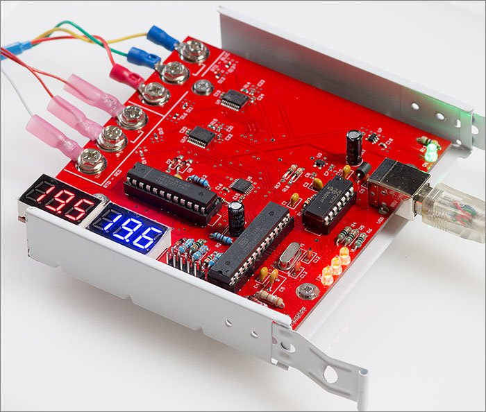
Installed into a hard drive caddy and powered up with two probes
I used two probes for testing. One was bought from Thermosense in the UK and the other one is a no-name cheapo probe from ebay. As you can see from the readings they perform very differently.
$ ./sendcommand /dev/Andy0 READINGS
50156:{"red":{"value":"20.017590","code":"0"},"blue":{"value":"24.796766","code":"0"}}
The Thermosense probe is showing an accurate reading of around 20C and the ebay probe is way off the mark. If the ebay probe is consistently off by a constant value then that’s something I can correct for using my firmware’s RCAL and BCAL commands. Here’s how I corrected the ebay probe:
$ ./sendcommand /dev/Andy0 "BCAL -4.79"
18061:"OK"
Now if I re-run the READINGS command I get a much better result.
$ ./sendcommand /dev/Andy0 READINGS
18088:{"red":{"value":"20.143177","code":"0"},"blue":{"value":"20.132557","code":"0"}}
The caveat to using this method of correction is that it only works when the offset from true value is a constant. If it’s non-linear then a full and time-consuming characterisation of the response would be required and for a cheap ebay probe that’s just not worth the effort.
For completeness, here’s a list of all the serial commands accepted by this firmware.
| Command | Parameters | Description |
|---|---|---|
| ID | Return the board identifier string. | |
| CAPS | Return the board capabilities. | |
| VER | Return the version numbers. | |
| COPY | Return a copyright statement. | |
| UPTIME | Return the uptime in milliseconds. | |
| READINGS | Return the last temperature readings. | |
| RCAL/BCAL | Return the red/blue calibration offset. | |
| RCAL/BCAL | decimal number | Set the red/blue calibration value. |
| RCALDATE/BCALDATE | Return the red/blue calibration date. | |
| RCALDATE/BCALDATE | 32-bit positive integer | Set the red/blue calibration date as a Unix time_t value. |
| SERIAL | Return the unique serial number generated for this board instance. | |
| ALARM | ON/OFF/FLASH | Change the state of the red alarm LED. |
| DISPLAYS | RED/BLUE/BOTH/NONE | Change which of the 7-segment LED displays to show. Temperature readings are unaffected. |
Limitations
The MAX31865 is known to be prone to self-heating in certain modes of operation. The issue is a side-effect of the way in which RTDs are sensed. To measure the resistance of the probe a small excitation current is transmitted through the probe tip and the voltage drop is measured. In the MAX31865 implementation they also pass the excitation current through the 400Ω reference resistor and measure the drop across that.
The problem is that passing a current through any resistor causes heating which is obviously a very bad thing for a temperature sensor and this is called self heating. To get around this devices such as the LTC2986 use an extremely small current and in my LTC2986 design I’ve been selecting 500µA from the configurable list. The MAX31865 generates a much higher current of 4mA for a PT100 so we must take care to keep the excitation current switched off between measurements and also to limit the measurement frequency to avoid the problem of self-heating. I poll the sensor at 1Hz.
Video
I put together a short YouTube video showing this board in operation. You can view it using the preview link below.
Spare blank boards for sale
I’ve got a few spare boards left over from the build that I’ll sell off for approximately what they cost me. I’d feel guilty though if I didn’t remind you that you can download the Gerber files yourself from my site and get 10 copies for less than US$5 plus delivery from China.
Final words
I didn’t really need to build this; but then I don’t need to build anything. This was a case of an itch that just needed to be scratched. I needed to know if the MAX31865 was any good and so I had to build this to find out. The answer I found is that it’s not bad at all. It’s cheap and it works as advertised. It’s certainly no LTC2986 but it’s a decent alternative if your needs are not at the high-end.
Please feel free to leave a comment down below or if you’d like to start a conversation then do head on over to the forum.