Tags
Related Posts
Share This


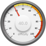
Project Difficulty
- All components are commonly available.
- The smallest IC pin pitch is 0.5mm
- The smallest discrete component is 0603.
- All components are on the top-side of the board
- The two oscillators have pads that are under the package
Recent Posts
A USB microphone for online meetings
Here in the UK the new reality of working in the IT business over the past year has been that we’re all at home working remotely over virtual desktop connections and for someone engaged in software development this is a setup that works well. Having to commute 90 minutes each way into London every day on the train is not something I’ll ever miss.
Team meetings are still an important part of the day though and that meant digging out and dusting off my old webcam, a Logitech something-or-other that works fine in every scenario except when I use it through my company’s Citrix-hosted virtual desktop. The video is fine but the audio frequency on the VDI is mismatched to the actual frequency on the physical device. I sound like Mickey Mouse on helium.
This is a well-known problem and the solution is to change the frequency on the VDI, which requires administrator level access. And that is never going to happen. I could try calling our support desk just to see how long it takes before they realise it’s not company-issued hardware and therefore the ticket has just been closed and is there anything else they can help me with today? No, not going to do that.
So I’ve been muddling through by using a rather useful Android USB microphone app called Wo-Mic. You install a PC server component, connect your phone by cable and voila your PC has a new USB microphone that’s actually your phone. It’s not a bad solution and the audio quality is very good but I’d really like a dedicated microphone that I can just plug in and place on the desk in front of my keyboard.
Any normal person would open Amazon and either buy the cheapest microphone available, or perhaps a Røde if they know decent audio when they hear it. Not me though. This sounds like a project if ever I heard one. A good chance to see if I can build a USB microphone and learn a thing or two along the way.
The design
I came up with two possible options for the design. One would be part-analogue and the other all-digital.
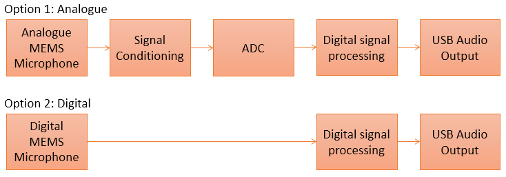
Both options are designed around a MEMS microphone for translating sound pressure levels into an electrical signal. Physically a MEMS microphone comes in a miniature metal ‘can’ that houses the required circuitry inside. The can serves both as physical protection for the sensitive receiver and as electrical protection from interference for the analogue circuitry. There is a small hole drilled in either the top or the bottom of the can to allow sound waves to enter.
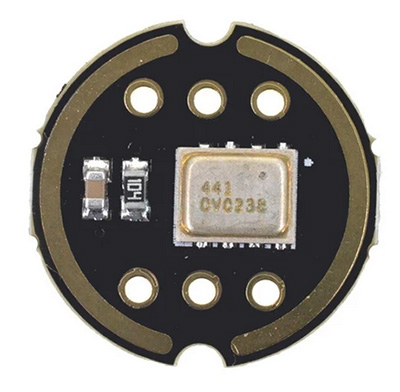
This is a TDK ICS43432
If the port is on the bottom then you need to provide a hole of the same size in your PCB. This is the most tricky design for a hobbyist to work with because you absolutely must not get any gunk in that port which means being super-careful where you put flux on the pads that will be very, very close by.
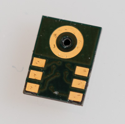
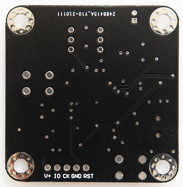
The tiny circuit board on the bottom with those difficult pads
In option 1, the part-analogue design, I would connect a MEMS microphone up to some analogue signal conditioning and amplification circuitry before feeding it to an AD converter and then into an MCU for digital signal processing and output over a USB interface using the USB audio device class.
The tricky parts in this design are the signal conditioning and the ADC. MEMS microphones output a very low AC signal typically around ±1V. This would need to be amplified using an op-amp before sending to an analog-to-digital converter. I’ve modelled this design in LT-Spice and am convinced that I could do it but the devil would be in the implementation details such as noise problems from the mixed-signal circuit board, choice of op-amp and ADC.
Option 2 does away with those tricky analogue signal conditioning parts and uses a digital MEMS microphone. These devices have the analogue processing inside the metal can and their output is a digital I²S signal. From a noise-reduction and signal quality perspective keeping those sensitive analogue parts inside the shielding of the can is the best decision.
I decided to go with Option 2, the all-digital (to me) design.
Selecting a MEMS microphone
ST’s range of digital microphones provide a PDM output which needs some fairly involved but perfectly do-able software decoding in the MCU to get the PCM samples that I need. Best though are the microphones from TDK and Knowles that provide an I²S output. I²S is supported in hardware by many of the STM32 devices (it’s just a specific application of SPI) so the microphone can be hooked up directly to the MCU and we’ll be provided with a constant stream of PCM samples that we can work with directly.
I’ve had mixed sucess in other projects where I’ve used these microphones. The first build I did was a total write-off because like a complete idiot I washed the board after building it, immediately destroying the microphone by getting water in the port. Undeterred I built another one and it did work but, being an analogue microphone the audio quality wasn’t great because my first attempt at filtering and amplification didn’t hit the mark.
The next board I built was a different design that used a Knowles I²S microphone and I had big problems getting it to reflow to the board. I think the metal can caused problems with heat transfer to the pads underneath. And that’s the crux of the problem – the pads are completely underneath the microphone so it’s impossible to check for bad joints. I decided that going forward I’d simply buy a breakout board with the microphone already on it and design a carrier board around it.
This is the one I decided to use. It’s the INMP441 by TDK, Invensense or whatever they’re calling themselves this week. It’s actually gone NRND now but that doesn’t matter because I’m not going into mass production and I can get these breakout boards on ebay for less than £5.
MCU selection
It’s an STM32 and that’ll come as no surprise to anyone that follows this blog because they’re just so versatile. I need one that has I²S and USB peripherals and will be capable of translating the I²S format into the USB format in real time. Since this is a one-off build overkill is not an issue so I’ve selected the STM32F446RCT7 in the LQFP64 package.
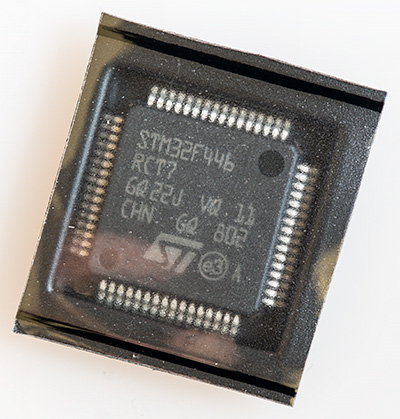
This has 256kB of flash, 128kB of SRAM and can run at up to 180MHz. A lot of those resources are going to go unused but for the sake of a few pounds I’d rather have resources to spare than find I needed more to complete the project.
Detailed design
Here’s a more detailed view of the proposed design.
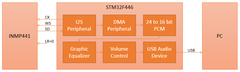
The STM32 sits at the center of the design and acts as an I²S master, providing the I²S clock and word select (WS) signals and receiving serial data as the response. Here’s a view of the protocol from the INMP441 datasheet.
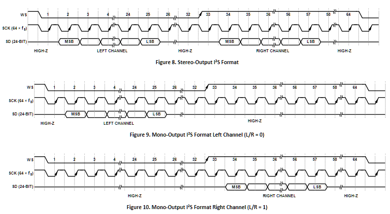
The protocol in the middle is the one I’ll be using
The STM32 will provide a 48kHz WS signal and since there are 64 clocks per period then the clock will be 3.072MHz. Providing this clock accurately with zero error will require a dedicated external oscillator that you will see in the schematic. The data from the INMP441 is provided as 24-bit signed PCM samples, MSB first and left-justified into 32-bit words. The data bits are offset by one clock from the change in the WS signal and are available to read on the rising edge of the clock. This is known as the ‘Philips’ standard. Presumably the one clock offset was to allow early hardware implementations to use a clock cycle to reset their registers and prepare for a new sample.
The I²S peripheral will be connected to the DMA peripheral so it can operate in ‘hands free’ mode. The firmware will receive interrupts when buffers of data are ready to be processed and sent.
A buffer of data from the microphone will be presented as 64-bit samples with 24-bits of data in the left channel and zero in the right channel. ST provide a reference implementation of the USB audio device class that operates on 16-bit samples and I’ve decided not to try to change that, at least not in my first release. Therefore the first task is to downsample the sparse array of 64-bit samples into a new buffer of 16-bit PCM samples.
The next task in the pipeline is to apply any ‘graphic equalizer’ filtering that might be required. For example I might need to suppress high or low frequency noise to clean the signal up. If I’m really lucky the signal will be perfect out-of-the-box but somehow I doubt it.
Secondly I’ll need to adjust the signal volume (amplitude) according to my preference. The USB audio device class provides for a volume control and PC operating systems expose that in the form of a microphone volume slider in their ‘settings’ control panels.
Finally the fully transformed buffer of PCM signals can be sent to the USB firmware for transmission to the PC.
All of this has to be designed so that the number of samples that we gather in one DMA buffer is sufficiently large that we have enough time to do all the processing before the next buffer is available but cannot exceed the maximum size permitted to be sent in a single USB packet. This is why I’ve selected a 180MHz CPU with DSP instructions — finding that I’m CPU-bound would be a show-stopper for the project.
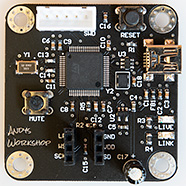
Schematic
Here’s the full schematic for this project.
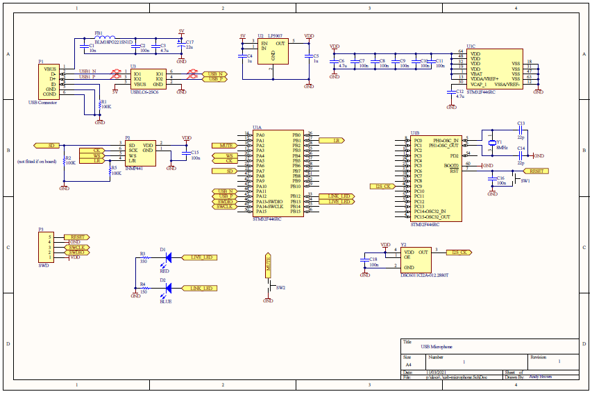
Click for a PDF
The schematic is quite modular in design so let’s have a walk-through of each section.
The power supply and USB connection
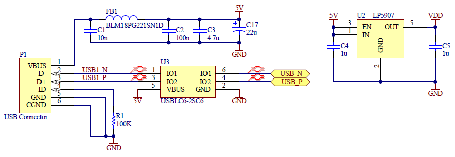
5V is delivered to the board over the USB cable, filtered through the usual LC network that I use and connected to a Texas Instruments LP5907 3.3v ultra low noise regulator. The USB data signals and the 5V input are passed through an ST Micro USBLC6 ESD protection IC.
The INMP441 microphone

The footprint for the INMP441 is just two rows of 3 female pin headers spaced at 300mil. L/R is pulled down to GND with R5 which should cause the INMP441 to output data in the left channel. Rather than leave this hardwired I also decided to connect it up to the MCU just in case I needed to assert manual control over that line.
The INMP441 specification requires a 100k pull-down on the SD line and when I wrote this schematic my INMP441 was on the slow-boat from China so I decided to include the footprint for R2 and if it turned out that the board included it then I’d leave mine off the final build.
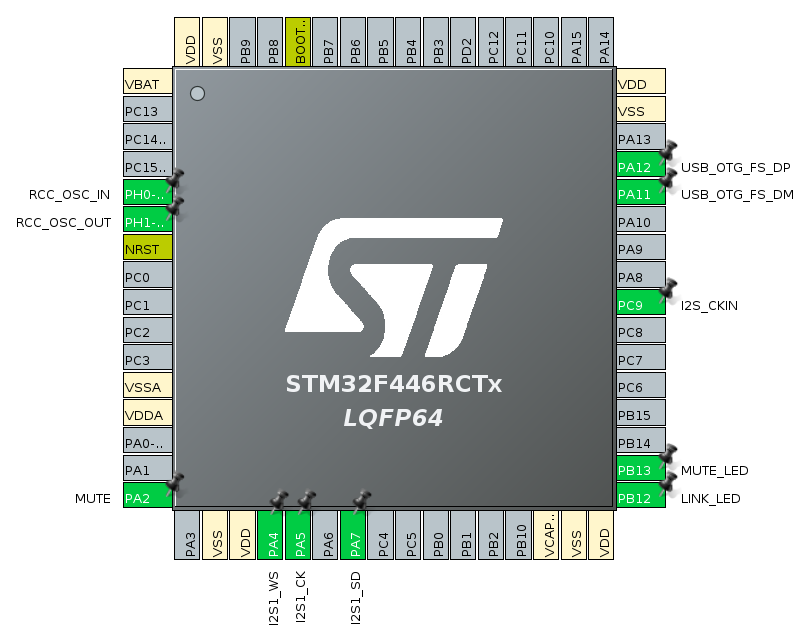
The STM32F446RC
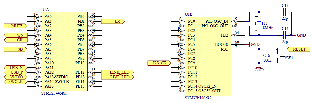
The smallest available LQFP package has 64 pins so lots of them are going to be unused. On the left side we’ve got the I²S signals connected to the I2S3 peripheral. There’s also a simple GPIO input for a physical mute button on board. When muting is enabled the device will ignore DMA interrupts. USB I/O and the necessary SWD programming ports complete the left side of the picture.
Two LED outputs are provided. The blue link LED will light when the USB connection is active and running. If there’s a software crash in the form of a hard-fault then I’ll rapidly flash this LED and to that end I’m providing a reset button that can be used to get me out of this situation without having to unplug the USB cable. The red live LED will light up when data is actively being sent over the audio connection. When software or hardware muting is enabled then this light will go out.
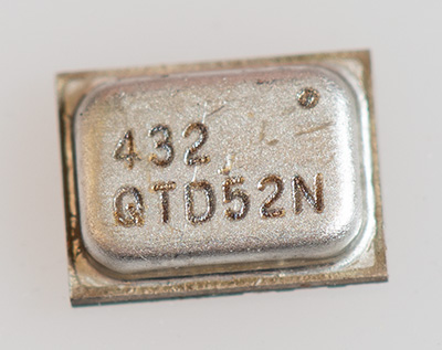
Optimum USB audio quality requires accurate clocks. I2S_CK on PC9 is one such clock. It’s connected to an external 12.288MHz Microchip oscillator. Internally the STM32 can divide this by 256 to get exactly 48kHz and by 4 to get exactly 3.072MHz.
The STM32’s core clock will be derived from an external 8MHz crystal that also guarantees an accurate 48MHz clock for the USB peripheral.
Bill of materials
Here’s the full bill of materials for this project.
| Identifiers | Value | Quantity | Description | Footprint |
|---|---|---|---|---|
| C1 | 10n | 1 | Ceramic capacitors | 0603 |
| C2, C7, C8, C9, C10, C11, C15, C16, C18 | 100n | 9 | Ceramic capacitors | 0603 |
| C3, C6, C12 | 4.7µ | 3 | Ceramic capacitors | 0603 |
| C4, C5 | 1µ | 2 | Ceramic capacitors | 0603 |
| C13, C14 | 22p | 2 | Ceramic capacitors | 0603 |
| C17 | 22µ | 1 | electrolytic capacitor | 2.5mm lead pitch |
| D1 | Live LED | 1 | Red LED | 2012 |
| D2 | Link LED | 1 | Blue LED | 2012 |
| FB1 | BLM18PG221SN1D | 1 | Ferrite bead | 0603 |
| P1 | USB connector | 1 | USB mini-B | custom |
| P2 | INMP441 | 1 | 2x 3-pin headers | 100mil headers, 300mil spacing between headers |
| P3 | JST XHP-5 | 1 | Female SWD header | 5x 2.5mm |
| R1, R2, R5 | 100k | 3 | Chip SMD resistor | 0603 |
| R3 | 330 | 1 | Chip SMD resistor | 0805 |
| P4 | 150 | 1 | Chip SMD resistor | 0805 |
| SW1, SW2 | 2 | PCB button | custom | |
| U1 | STM32F446RCT7 | 1 | MCU | LQFP64 |
| U2 | LP5907 | 1 | LDO regulator | SOT23-5 |
| U3 | USBLC6-2SC6 | 1 | USB ESD protection | SOT23-6 |
| Y1 | Abracon ABM3B | 1 | 8MHz crystal | custom |
| Y2 | DSC6011CI2A-012.2880T | 1 | Microchip 12.288MHz oscillator | custom |
PCB layout
Before starting the layout I had a quick look at the current JLCPCB prices and could scarcely believe my eyes when I saw that controlled impedance 4-layer boards are available up to 100x100mm for just $8 a pack of five. It wasn’t that long ago when 4 layer boards would run into hundreds of dollars!
Are 4-layer boards going to be the new normal? They are for me that’s for sure. The benefits of being able to just drop a via when you need power or ground are hard to ignore. The only minor annoyance with JLPCB’s implementation is that they won’t accept a negative gerber for an internal plane. You have to do everything with polygons and fills.
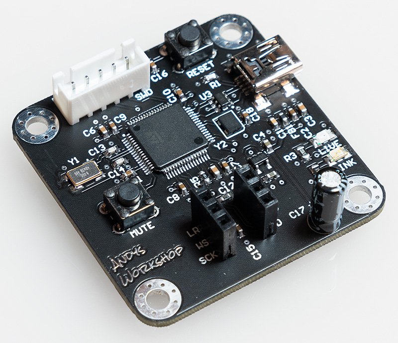
Here’s the PCB layout.
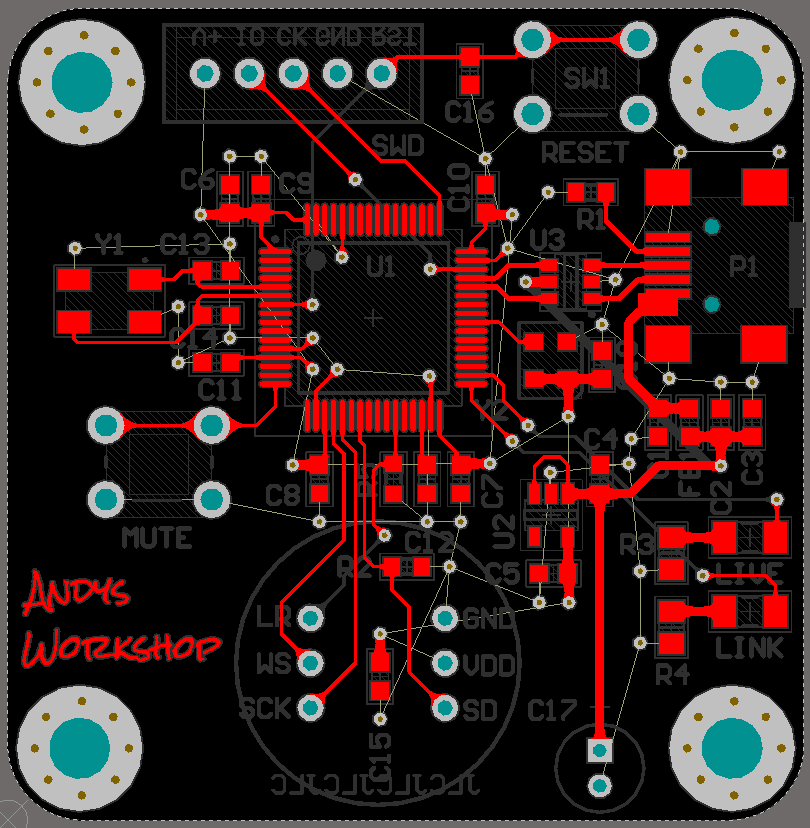
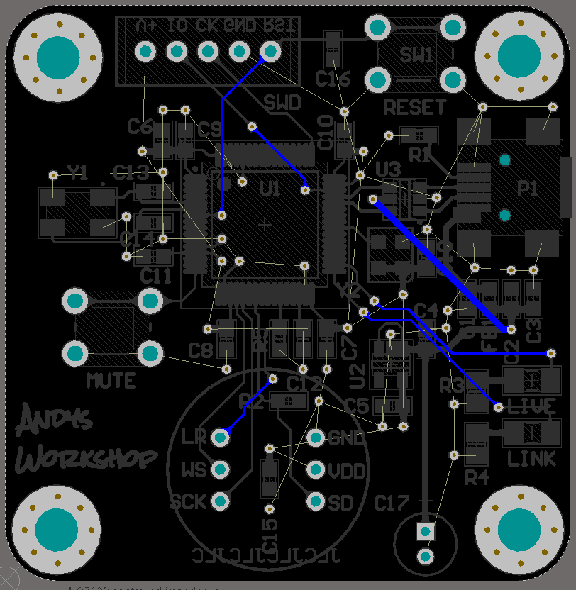
I shelved the polgon pours, including the two internal pours for these screenshots hence the rats-nest of apparently unconnected nets.
The first internal layer is GND and the second is VDD. The layout of the header pins for the INMP441 is designed so that the hole in its board that allows sound to pass through into the microphone can is facing upwards. I do have some concerns about dust getting into that hole over time so I may have to consider a housing for the microphone with some foam over that area.
The 5-pin SWD connector is a female JST XHP-5. These box connectors have a 2.5mm pitch and mate with a male connector fitted to a custom cable that I’ve made up. I now use these connectors for SWD connections when the board is small and won’t take the much bigger 10×2 100mil headers.
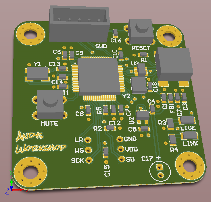
The 3D view is best for checking whether any of the silkscreen labels overlap parts that they should not and making minor changes to their position. Four M3 screw holes round off a very simple physical design measuring around 46mm square.
Building the board
I uploaded my design to the JLPCB website, selected a black solder mask and used the 3 weeks it took to arrive to source the parts from Mouser.
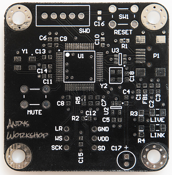
JLPCB were the first to offer a matte-black soldermask at a reasonable price and I do have one of their early boards and the finish was very similar to a black chalkboard. Apparently that finish suffered from poor adhesion and so they’ve now changed it slightly and whilst it’s still matte there’s a very slight shine to it and it’s more black than grey. It does look very nice and not at all like the horrible glossy uneven black of old.
My process for building a board is quite slow but I find it reliable. I first tin the pads with solder, then I reapply flux to the pads, then I place the surface mount components on the tinned pads and then I reflow the board in my halogen reflow oven. When the reflow is complete I touch up any problems manually and then solder in the through-hole components by hand. Finally I wash the board using hot soapy water and a toothbrush, rinse it off with cold water and leave it out to dry for at least a day.
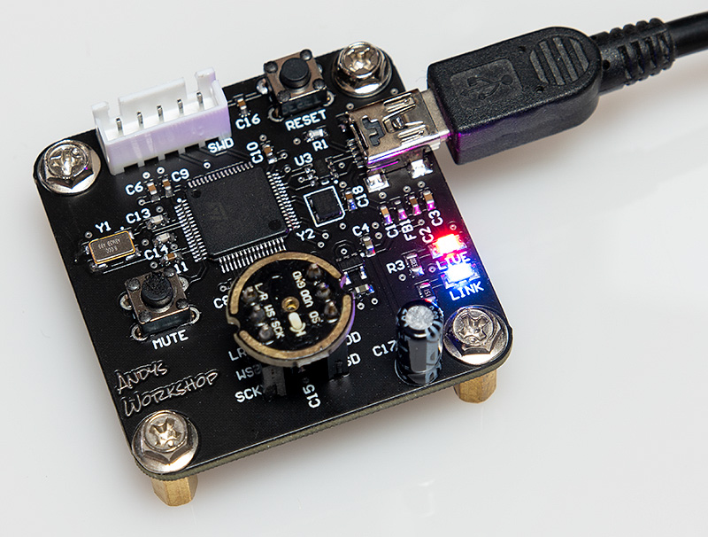
Looking good! The reflow was completely successful with no touch-up required. Now I can get on with the firmware development.
Firmware
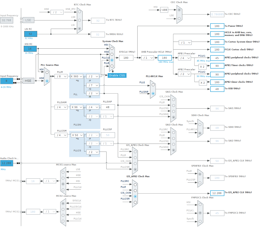
I wrote the firmware in Ubuntu Linux using the STM32Cube IDE. This is basically Eclipse with plugins developed by ST Micro as well as some other open-source plugins. To kick-start the project I used the Cube GUI to configure the peripherals and clocks and then write out a template project. Here’s the peripherals view:
It’s very helpful to be able to use the graphical clock tree configurator to set everything up and know in advance that it’s going to be perfect.
Once Cube has generated the template project then I take it from there. I edit the generated source code to remove the huge ugly (sorry ST) comments and reformat the source to make it more readable.
Debugging
The first time I hooked everything up I was initially pleased to find that the MCU was responding, firmware was being flashed and I was getting regular interrupts from the DMA controller handling the I²S peripheral. On the USB side my microphone was detected by Ubuntu and I was able to capture samples using the free Audacity software.
However, it sounded dreadful. My voice was audible but it was harsh and way too loud. If I got anywhere near the microphone then it would clip badly and harshly. Something was clearly wrong.
The difficulty with debugging audio is that you’re presented with a continuous stream of what you have to assume is valid PCM samples but what does a correct sample look like? You can’t just look at a buffer of data in the debugger and be able to tell good from bad. I’ve been known to hold up the microphone to my computer speakers whilst playing an online sine-wave generator to see if the captured data would exhibit a constant pattern!
The first thing I did was verify what could easily be probed. The voltages were fine. My oscilloscope showed exactly 48kHz on the WS line and exactly 3.072MHz on the CK line so no problems there.
To rule out the microphone I ordered another one online from a different seller and waited a few days. The new microphone showed exactly the same issue so it was apparent that the problem was elsewhere.
For the next step I decided that I needed to know exactly how the DMA peripheral was delivering the I²S data into memory. I could see from the data in-memory that the first 32-bit word had the data and the second was always zero but was the 24-bit sample in the 32-bit double-word being byte-swapped or swapped around 16-bit words? This was a nagging concern that had to be investigated because the DMA peripheral is programmed for 32-bit transfers but the I²S peripheral is inherently a 16-bit device.
I got out an old STM32F4 discovery board and wrote a simple firmware program to act as an I²S slave that would output fixed 24-bit samples. I removed the INMP441 from my board and hooked up the discovery board, splicing in my logic analyser into the middle so I could see what was going on.
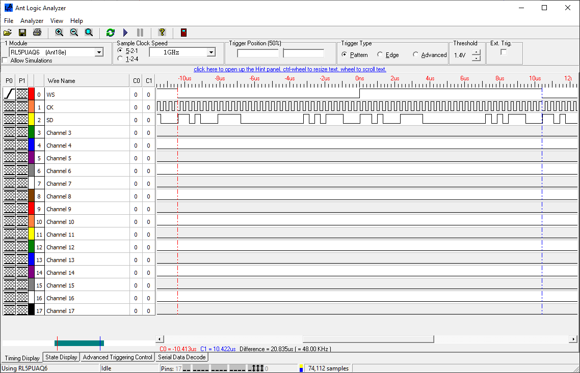
This was very enlightening. Not only could I see exactly how a 24-bit value in memory is placed on to the wire by the I²S peripheral in the discovery board but I could also see how that would end up in the receiving board’s memory.
The issue, in the end, was that I was losing the sign bit on the PCM sample during my processing. To downsample from 24 to 16 bits I simply take the top 16-bits, discarding the lower 8. With the sign bit preserved correctly the audio started working.
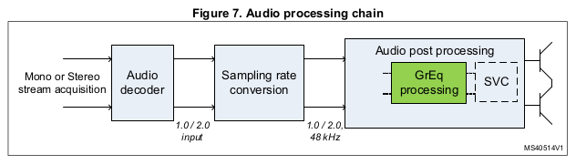
Audio processing
ST provide a suite of audio effects expansion software called X-CUBE-AUDIO. This is implemented as a closed-source but freely available package that integrates easily into firmware using consistent APIs designed to be used as part of an audio-processing pipeline.
The first package I was interested in was the Graphic Equalizer (GREQ) package documented in UM1798. The audio that I was sampling was clear and noise-free but because of the location where I sit it tended to sound quite boomy and bass-heavy. If I could attenuate those frequencies then my speaking voice would sound more crisp and natural with less reverberation.
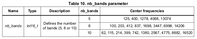
You can select the center frequencies for the equalizer configuration from 5, 8 or 10 preset bands with a maximum adjustment of ±12dB. I selected 10 bands and configured it to attenuate 62, 115 and 215Hz by -6dB and to amplify the other frequencies by +6dB. The reason for the amplification of the higher frequencies is to compensate for an overall attenuation performed by the filter — see UM1798 for details.
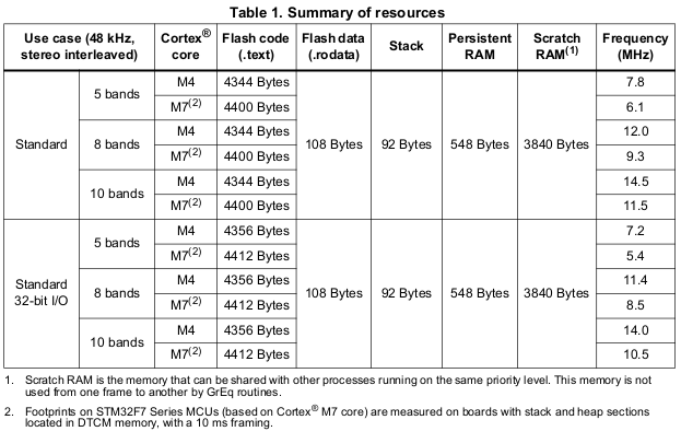
This is the resource usage required by the GREQ filter.
To use the filters I simply copied the two header files and the binary library into my project, rebuilt and ran. Surprisingly and very happily it just worked first time. The audio was notably more clear with much less unwanted boomy reverberation.
I will have to leave these settings hardcoded into the firmware because although the USB audio device class does provide for graphic equalizer control I have not seen it implemented in PC operating system software even though I declare in my audio device descriptor that I support it and I can see it there in the UsbTreeView PC software.
The next part would be volume control. Until now I’d used the normalisation filter in Audacity to bring up the input signal to a loud enough level to listen to critically. This stage in the pipeline is achieved by ST’s Smart Volume Control (SVC) filter documented in UM1642.
It is possible to do dumb amplification by simply multiplying the PCM signals by a constant value and if the levels are low enough you might get away with that without clipping but you’ll also amplify any noise in the signal because you’ll treat low levels where there is no useful sound the same as the higher levels. ST’s filter takes into account the dynamic range of the input signal to give more consideration to the peaks without touching the troughs.
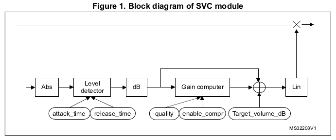
The configuration for this filter is a simple selection of the gain from -80 to +36dB in 0.5dB steps so the actual limits for the parameter are -160 to +72. This is the resource usage required by the SVC filter.
Once again this just worked and I was able to hook up the volume control to the USB control input so I could use the volume slider in the Ubuntu settings app to set it on-the-fly.
I have found that I need to apply the full +36dB amplification to get acceptable volume from the microphone. I used the Skype echo test call to check that I’m sounding good and, Skype’s obvious compression of the voice channel aside, it’s all good on the audibility front.
Here’s the important interrupt handler that processes the incoming samples.
/**
 * 1. Transform the I2S data into 16 bit PCM samples in a holding buffer
 * 2. Use the ST GREQ library to apply a graphic equaliser filter
 * 3. Use the ST SVC library to adjust the gain (volume)
 * 4. Transmit over USB to the host
 *
 * We've got 10ms to complete this method before the next DMA transfer will be ready.
 */

inline void Audio::sendData(volatile int32_t *data_in, int16_t *data_out) {

  // only do anything at all if we're not muted and we're connected

  if (!_muteButton.isMuted() && _running) {

    // transform the I2S samples from the 64 bit L/R (32 bits per side) of which we
    // only have data in the L side. Take the most significant 16 bits, being careful
    // to respect the sign bit.

    int16_t *dest = _processBuffer;

    for (uint16_t i = 0; i < MIC_SAMPLES_PER_PACKET / 2; i++) {
      *dest++ = data_in[0];     // left channel has data
      *dest++ = data_in[0];     // right channel is duplicated from the left
      data_in += 2;
    }

    // apply the graphic equaliser filters using the ST GREQ library then
    // adjust the gain (volume) using the ST SVC library

    _graphicEqualiser.process(_processBuffer, MIC_SAMPLES_PER_PACKET / 2);
    _volumeControl.process(_processBuffer, MIC_SAMPLES_PER_PACKET / 2);

    // we only want the left channel from the processed buffer

    int16_t *src = _processBuffer;
    dest = data_out;

    for (uint16_t i = 0; i < MIC_SAMPLES_PER_PACKET / 2; i++) {
      *dest++ = *src;
      src += 2;
    }

    // send the adjusted data to the host

    if (USBD_AUDIO_Data_Transfer(&hUsbDeviceFS, data_out, MIC_SAMPLES_PER_PACKET / 2) != USBD_OK) {
      Error_Handler();
    }
  }
}

/**
 * Override the I2S DMA half-complete HAL callback to process the first MIC_MS_PER_PACKET/2 milliseconds
 * of the data while the DMA device continues to run onward to fill the second half of the buffer.
 */

inline void Audio::I2S_halfComplete() {
  sendData(_sampleBuffer, _sendBuffer);
}

/**
 * Override the I2S DMA complete HAL callback to process the second MIC_MS_PER_PACKET/2 milliseconds
 * of the data while the DMA in circular mode wraps back to the start of the buffer
 */

inline void Audio::I2S_complete() {
  sendData(&_sampleBuffer[MIC_SAMPLES_PER_PACKET], &_sendBuffer[MIC_SAMPLES_PER_PACKET / 2]);
}
The DMA peripheral is configured to transfer 20ms of data into our buffer and to provide 'half-complete' and 'complete' interrupts. Therefore we have 10ms to decode, process and send 10ms of data before the next interrupt happens.
The first stage decodes the 64-bit mono samples from _sampleBuffer into 16-bit interleaved stereo signals in _processBuffer. Stereo is required because the GREQ filter will not operate on mono. To simulate stereo I simply duplicate the left channel into the right.
The second stage calls the GREQ filter to process the data in-place. Nice that these filters can work on data in-place.
The third stage calls the SVC filter to also process the data in-place.
The final stage takes the processed left channel from _processBuffer, copies it into _sendBuffer and calls USBD_AUDIO_Data_Transfer to transmit it. USBD_AUDIO_Data_Transfer has some constraints. It cannot be called more frequently than once per millisecond — check. You must pass it an amount of data that matches the calling frequency — I'm calling it once every 10ms with 480 mono samples which is exactly correct for a 48kHz stream. There may also be an upper cap of 1000 bytes on the packet to match a USB buffer size but that's not documented in the ST source code.
Performance
To measure the performance of the audio transformation and processing pipeline I inserted some debug code to toggle a GPIO pin at the start of the sendData method and then again just after the call to USBD_AUDIO_Data_Transfer. The actual data transfer performed by USBD_AUDIO_Data_Transfer is interrupt-driven so that part is not included in the performance figures. I used my oscilloscope to probe the oscillating GPIO pin and measured the time between the rising and falling edges.
Recall that I have 10ms to do all the work in the interrupt handler. In debug mode processing takes 1.7ms. In release mode it takes 1.5ms. I'm pleasantly surprised by this performance and it does indicate that the opaque audio processing blocks provided by ST Micro perform very well.
Watch the video
I've made short video that talks about this project and shows the microphone in operation with some sound samples so you can hear it.
It looks better when viewed directly from the YouTube website. Click here for that.
Free gerber files
If you'd like to build this board yourself then you can download the Gerber files from here. These can be uploaded to the JLPCB website.
Free firmware
It's all available on Github. Click here to go to the repository.
Update Aug 2021
I've just posted an article that explains how I fixed an issue with the click of the mute button being audible. Click here to read it.