Tags
Related Posts
Share This


Project Difficulty

Recent Posts
A high current power supply built around a server voltage regulator
Regular readers of this blog will have already seen the article that I published about 4 months ago where I attempted to reverse engineer a voltage regulator module originally designed to fit into a Dell server. The theory was that these would be high quality, stable and robust designs that could prove useful if I could figure out how they worked. They’re certainly worth far more than the few pounds that you can get them for on ebay today.
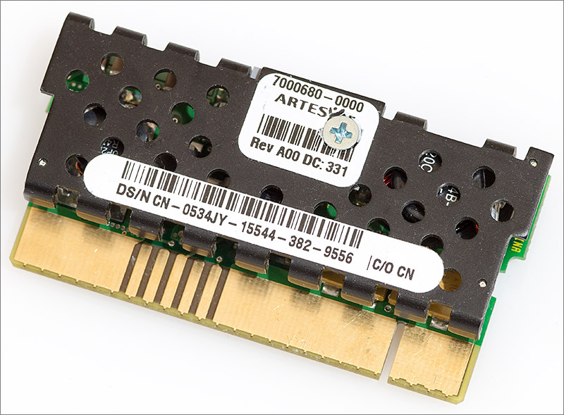
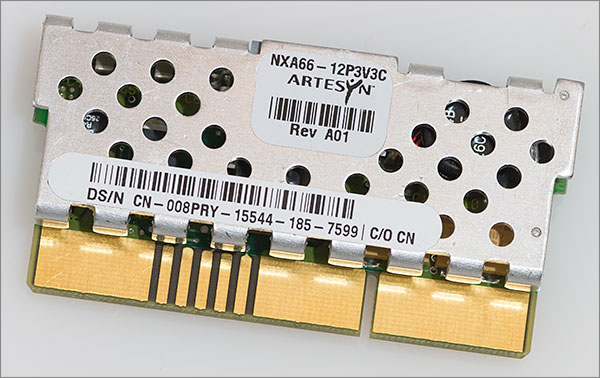
I was able to determine the function of the key pins on the module myself by experimentation and then with some help from eagle-eyed readers out there on the internet we were able to identify the module as an Artesyn NXA66 and subsequently a summary datasheet was located that provided the full pinout. To summarise, the main features of the module are:
- Selectable voltages of 3.3V and a ‘secondary’ level selectable by the VSP pin.
- 12V input level.
- 20A (66W) continuous current delivery at the 3.3V level.
- Output enable pin.
- ‘Power Good’ output signal.
- Differential remote sense.
- Ability to chain the modules to share current delivery.
It’s worth expanding a little on that ‘secondary’ voltage capability. I now have a few of these modules and some of them have a secondary level of 5V and others have 2.5V. All of these levels are useful but I suspect that if you’re planning to follow the design outlined here then you’ll want the 3.3V/5V module.
I don’t know of a foolproof method of differentiating the two modules from their ebay listings. What I can say is that the model with the black heatsink reviewed in the original article is a 5V module and all those that I received with a silver heatsink are the 2.5V module.
Designing a power supply controller
I decided that the best way to exploit the results of the reverse engineering effort was to design a controller board that would host the NXA66 and expose its functionality via a front panel. I’d throw in a few simple extras myself such as current monitoring and data logging and finally I’d implement it as a through-hole design so that it could be implemented by people of all skill and equipment levels.
The end result will be a bench-power supply that’s cheap to build and has a current supply level greater than that of most supplies priced at hobbyist levels.
Schematic
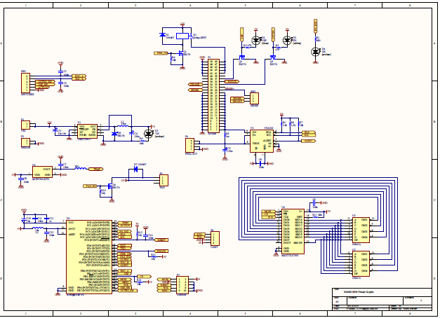
Click on the thumbnail for a PDF schematic
It’s a relatively simple and modular schematic. Let’s take a look at each of the modules in turn and describe the functionality in more detail.
Power input and control
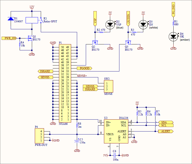
The input to this design is 12V which I envisage to be supplied by a commonly available power brick. Care needs to be taken to choose a supply that can deliver the current required by your output load. At the high end 66W at 3.3V equates to 5.5A at 12V plus losses, plus consumption by the controller itself. If you plan on providing 66W to your load then you’d want at least a 7A 12V supply on the input.
I’ve included a relay between the 12V input and the NXA66 because I don’t want the module powering up by itself without being co-ordinated by my controller. I discovered during experimentation that the module goes into an undefined state if you attempt to switch between the two available voltage levels while the power is on and for that reason I want to be able to set the control pins to the desired state and then power up the module. If the user decides to switch voltages while power is on then I’ll programmatically cut the power, set the VSP pin accordingly and then power up the module. A power MOSFET could be used equally well for this switching purpose; I tossed a virtual coin and it came down on the side of the relay.
All the functionality of the module is exposed to the controller. The slot itself is a 2×25 card edge connector with a 2.54mm pitch and an inter-row spacing of 5.08mm. The VSP and OUTEN pins are switched by MOSFETs and linked directly to LEDs that show their current state. Artesyn hint at a requirement for an output capacitor in their datasheet so I include a 150µF electrolytic at the output terminal. The output and return terminals themselves are doubled up to provide a higher current carrying capacity.
PGOOD is an open-drain (or collector) output. This means that the module can drive it low but it floats when high so it must be pulled up to a high level by the controller. Open-drain outputs are used when the I/O levels of the controller are not known by the designer. It would be no use specifying this output as a push-pull pin at 12V when the MCU on the board is 3.3V, for example. I connect PGOOD to the MCU with a pull-up resistor and use a separate MCU pin to light the indicator LED.
Current monitoring is provided by the Texas Instruments INA226 in a surface mount MSOP-10 package with a 0.5mm pin pitch. Sorry about that. Try as I might I just couldn’t find a suitable current monitor in a DIP package that came close to the capabilities of this little chip. This is the only SMD package on the board.
The INA226 continually senses the voltage across a very low value (2mΩ) resistor placed in the path of the output current. An internal ADC converts this to a digital value that can be queried by an MCU using the I2C protocol. You can set an internal calibration register for fine tuning the current reading to compensate for the inaccuracy inherent in the sense resistor value. As well as the current you can also query the sensed voltage and the power. It can also alert you via an output pin if a voltage or power threshold that you program is exceeded. This is all great stuff and is ideal for this project.
The Microcontroller
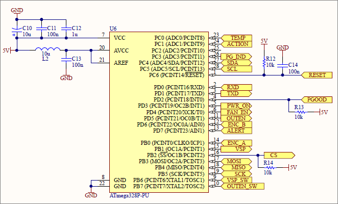
Really, It had to be an Atmega didn’t it? The requirement for a though-hole design rules out the STM32 F0, my favourite general-purpose ‘do almost anything’ MCU. This design will use the same Atmega328p made famous the world over by thousands of Arduino users. That same level of success means that you can pick up this MCU for just a few dollars from your favourite components store.
There are a few points to note about how the MCU is configured in this design. Firstly I’m using the internal 8MHz oscillator as the clock source which, given the documented 10% tolerance, does pose a risk to the ability to run a reliable UART for data logging. If I do revise this design then I will try to squeeze in an external crystal. Secondly, since I’ll be using the ADC there is an LC filter on AVCC which will also be used to set the AREF level.
5V voltage regulator
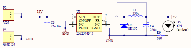
The MCU and the external peripherals on this board all run at 5V so I need to drop the input level of 12V down to 5V to generate that supply. A 7V difference means that a linear regulator would be burning off a lot of power as heat so for efficiency reasons a switching buck regulator is the preferred option. I opted to use the Texas Instruments LM2574 Simple Switcher that can provide up to 500mA which should be more than enough for this design. TI’s Simple Switcher range are very reliable and easy to use. I’ve used them many times in the past and never had any issues with stability.
Display and user interface
The readout for a power-supply, or any bench instrument for that matter, needs to be LED, OLED or VFD. In my opinion LCD lacks the eye-catching ‘at a glance’ contrast of LED or VFD. VFD is beautiful to look at but expensive to buy in module form. Small OLED modules are available cheaply and were a contender for this design but I decided to go for two 4-digit 7-segment LED modules.
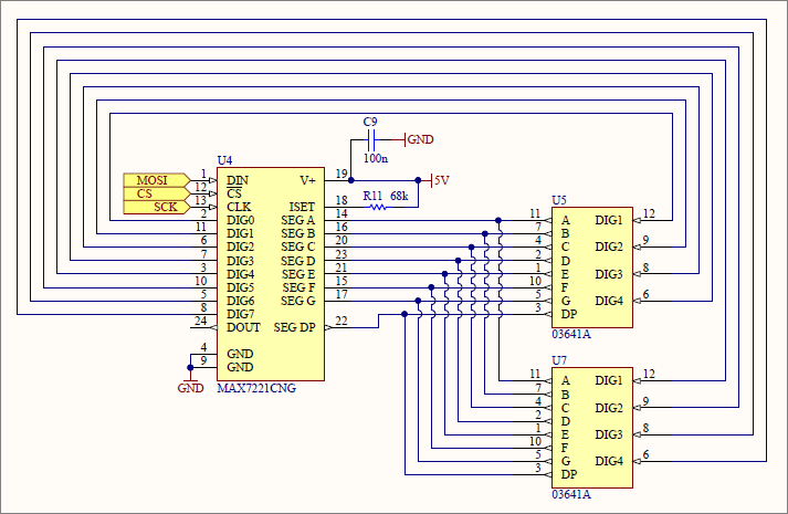
The controller is the MAX7221 from Maxim. This controller can multiplex 8 LED digits, it’s available in a DIP package and information about its usage is readily available on the internet. Basically you just send it a digit number and the state of the segments for that digit and it will hold the digit in that state without intervention until you come back and tell it a new state. Easy.
During normal operation the voltage and current readouts from the INA226 will be continuously displayed on each of the modules. I will reuse the displays as a rudimentary UI to set configurable parameters for this controller. These modules are a common-cathode design and are readily available on ebay. I’ll go into more detail in the bill of materials section.
Temperature sensing and fan control
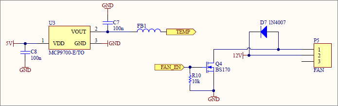
There’s a heatsink built in to the NXA66 for a good reason. At the higher current levels the module will need to dissipate a significant amount of heat. To help with that I’ve included a temperature sensing module and fan controller. The MCP9700-E/TO is a thermistor in a TO-92 package that outputs a voltage proportional to the temperature that it senses.
I plan to tape this sensor to the heatsink of the NXA66 right above the power MOSFET. The sense voltage will be fed to the ADC on the Atmega328p where it will be converted into Celsius. If the temperature exceeds a preset value then a standard 12V 40mm DC fan will be switched on until the temperature drops back below another threshold.
As with anything ADC-related the sensed reading as well as the ADC supply and reference level need to be carefully filtered to avoid erroneous readings due to noise and glitches on the lines.
UART
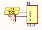
Not a lot going on here. It’s a simple breakout of the pins on the Atmega328p. I will attach these to one of those small external UART driver boards that you can get on ebay. The MCU will continually output the voltage and current readings so that you can collate them on a PC for data logging.
USBASP
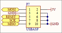
This is the programming header. The pinout exactly matches that of the USBASP programmer so it can be directly plugged on to program the MCU.
Switchgear
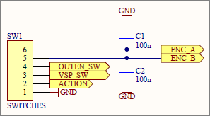
The front panel of this PSU will have SPST toggle switches for output-enable and voltage-select functionality. There will also be a rotary encoder with a built-in push-button function that I will use for adjusting the configurable controller parameters.
Both switches and the button are normally-open and will connect to ground when closed. Each one is attached to an input pin on the MCU that has its internal pull-up enabled meaning that it will read high when the switch is open and low when it’s closed. Wiring is simplified because after connecting one pin of each switch/button to the correct MCU input pin all the remaining pins are then common’d together and connected to a ground terminal.
Bill of Materials
Here’s a complete bill of materials for this project. Where a component is available from Farnell I’ve included the order code.
| Designator | Value | Quantity | Footprint | Description | Farnell Order Code | Notes |
|---|---|---|---|---|---|---|
| C1, C2, C6, C7, C8, C9, C11, C13, C14 | 100n | 9 | 2.54mm lead spacing | Ceramic capacitor | 2309020 | |
| C3 | 22u 16v | 1 | 2mm lead spacing | Polarized Capacitor (Radial) | 1870976 | |
| C4 | 220u | 1 | 2.5mm lead spacing | Polarized Capacitor (Radial) | 1902883 | |
| C5 | 220u | 1 | 2.5mm lead spacing | Polarized Capacitor (Radial) | 1902883 | |
| C10 | 10u | 1 | 2mm lead spacing | Polarized Capacitor (Radial) | 1902913 | |
| C12 | 1u | 1 | 5.08mm lead spacing | Capacitor | 2112910 | 1 |
| D1, D7 | 1N4007 | 2 | DO-41 | 1 Amp General Purpose Rectifier | 2317417 | 2 |
| D2 | 1 | LED-3MM | 3mm LED | 3 | ||
| D3 | 1 | LED-3MM | 3mm LED | 3 | ||
| D4 | 1 | LED-3MM | 3mm LED | 3 | ||
| D5 | 1 | LED-3MM | 3mm LED | 3 | ||
| D6 | SR150 | 1 | DO-204AL | Schottky Rectifier | 1861420 | |
| FB1 | BLM18PG221SN1D | 1 | AXIAL-0.3 | Inductor | 2292304 | |
| K1 | OJE-SS-112HMF,F000 | 1 | Relay TE OJ/OJE | Single-Pole Single-Throw Relay | 1891668 | |
| L1 | RLB0914-331KL | 1 | RADIAL 5x9x9.5 | Inductor | 2309243 | |
| L2 | RLB0712-100KL | 1 | RADIAL 10x7.2x3 | Inductor | 2434811 | |
| P1 | Edge connector | 1 | 2x25 | 2.54mm pitch, 5.08mm row spacing | 4 | |
| P2 | PM5.08/2/90 | 1 | PCB terminal block - 2 pin | WEIDMULLER PM5.08/2/90 | 1131855 | 5 |
| P3 | PM5.08/2/90 | 1 | PCB terminal block - 2 pin | WEIDMULLER PM5.08/2/90 | 1131855 | 5 |
| P4 | PM5.08/2/90 | 2 | PCB terminal block - 2x2 pin | WEIDMULLER PM5.08/2/90 | 1131855 | 5 |
| P5 | Fan header | 1 | HDR1X3 | Header, 3-Pin | 588581 | |
| P6 | 1 | 2.54mm | Header, 4-Pin | 6 | ||
| P7 | 1 | 2.54mm x 2 | Header, 5-Pin, Dual row | 6 | ||
| Q1, Q2, Q3, Q4 | BS170 | 4 | TO-92 | N-Channel MOSFET | 1017687 | |
| R1, R9 | 680 | 2 | AXIAL-0.3 | Resistor | 2329545 | |
| R2, R3 | 470 | 2 | AXIAL-0.3 | Resistor | 2329531 | |
| R4, R7, R10, R12, R13, R14 | 10k | 6 | AXIAL-0.3 | Resistor | 2329474 | |
| R5, R6 | 2.2k | 2 | AXIAL-0.3 | Resistor | 2329584 | |
| R8 | 2m 1% | 1 | 2512 | Welwyn ULR2-R002FT2 | 1292491 | |
| R11 | 68k | 1 | AXIAL-0.3 | Resistor | 2329546 | |
| SW1 | PM5.08/2/90 | 3 | PCB terminal block - 3x2 pin | WEIDMULLER PM5.08/2/90 | 1131855 | 5 |
| SW2 | 1 | PCB terminal block (3 pin) | Header, 3-Pin | 7 | ||
| U1 | LM2574N-5.0/NOPB | 1 | DIP-8 | 0.5A Step-Down Voltage Regulator | 1469169 | 8 |
| U2 | INA226AIDGST | 1 | MSOP-10 | Current Sense Amplifier | 1924807 | |
| U3 | MCP9700-E/TO | 1 | HDR1X3 | MCP9700 plus fan-style header | 1332166,588581 | 9 |
| U4 | MAX7221CNG | 1 | DIP-24 | 8-Digit LED Display Driver | 10,8 | |
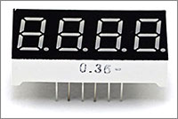
| U5, U7 | 03641A | 2 | 0.36" 12 pin | 4 digit 7 segment LED common cathode | 410561X | 11 |
| U6 | ATmega328P-PU | 1 | DIP-28 | 8-bit AVR Microcontroller | 1715487 | 12,8 |
Notes
Some of the components have note numbers against them. The following numbered paragraphs correspond to a numbered note in the bill of materials table.
- 2.54mm parts can also be used if you carefully bend the leads outwards to fit the wider 5.08mm pitch.
- Any of the 1N400x series will be fine. They all cost about the same so I tend to keep a stock of the biggest one, the 1N4007 around.
- Any colour of 3mm LED will work. I’ve used amber for Power/PGOOD, white for EN and blue for VSP for no other reason than I felt like it.
- This can be a tricky one. I got the edge connector on ebay, item number 140888533934. Part 2668415 at Farnell looks like it could be persuaded to fit – the row pitch is only 0.2mm off the required 5.08mm.
- PCB terminal blocks with the 5.08mm pitch are plentiful on ebay and they slot together to form longer blocks. There’s no reason not to use the cheaper ebay blocks for the switchgear but I would stick to a quality item for the power in/out blocks (P2, P3 and P4).
- The male 2.54mm pin headers are at their cheapest on ebay.
- The 3-way 5.08mm PCB terminal blocks are available on ebay.
- I mount all my ICs in sockets. You don’t have to but if you need to replace one…
- I’ve included a 3×2.54mm header footprint for the TO-92 temperature sensor and I chose to use a 3-pin fan header as the connector. You could just as easily use male and female pin headers if you have them, or even solder the sensor wires directly to the board as the most economical method.
- The MAX7221CNG is available cheaply on ebay in lots of 5. As usual with ebay there’s a good chance of them being clones but that’s where I bought mine from and they seem to work.
- The 7-segment 0.36″ LED display is available from many ebay sources. Make sure it’s a common cathode configuration. These displays all seem to share a common pinout, but just in case click here to see the datasheet for the one that I bought.
- You can probably buy an Arduino clone on ebay from China with an Atmega328P on board for less than Farnell will charge you for one piece of the IC alone.
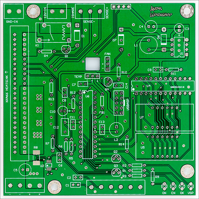
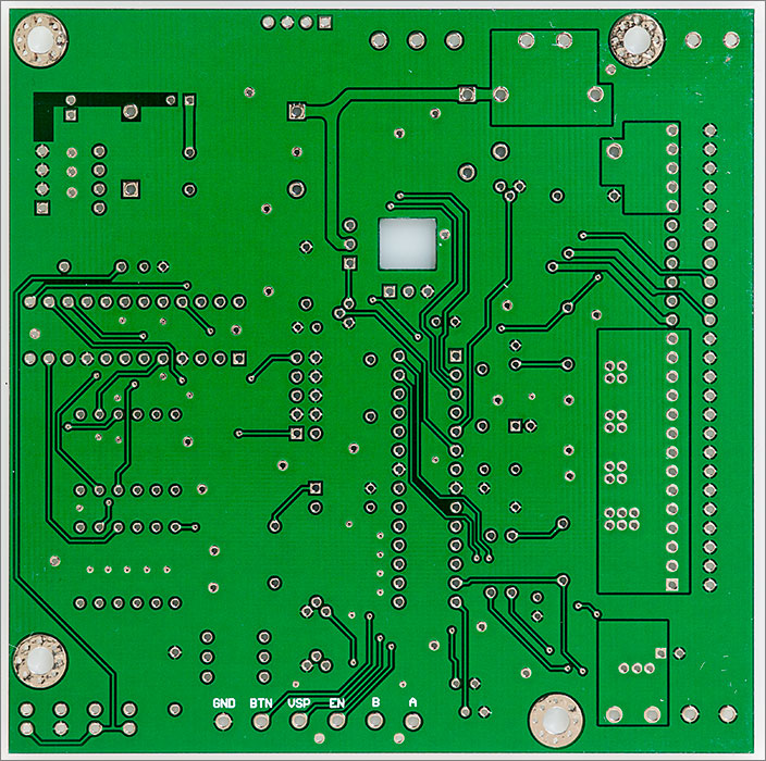
PCB layout
The PCB was laid out to fit the 10x10cm shape that’s so economical to produce at the Chinese prototype houses. The NXA66 sits on the left with a direct, wide path along top and bottom ground fills from the current return terminal to the ground entry point. Further optimisation could be made here by ignoring the return ground terminals and wiring from the front panel ground directly back to the power entry ground at the back.
Indicator LEDs and switchgear terminals are placed at the front and power entry is at the back. I will place a 2.1mm panel-mount connector on the back of the case as well as an on-off switch.
The 3-pin fan and temperature connectors surround a rectangular cutout in the PCB. The cutout is designed for routing the wires from the sensor and fan below the board for aesthetic reasons.
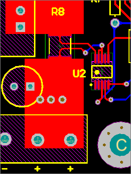
The regulator output runs through top and bottom polygons to the sense resistor where it unavoidably shrinks to pass through the component whereafter it expands to a pair of polygons connected to dual output terminals. The INA226 is placed as close as possible to the sense resistor.
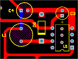
I mentioned earlier that the TI Simple Switcher regulators are an easy to use design, and they are, but good practice is still in order when laying out the components that take part in the switching loop.
TI’s application note AN-1229 covers it all but the basics are that the switching components should be placed as close to the regulator as possible (tricky with through hole), they should be arranged in the order shown in the schematic and the ground returns for each of them should be tied together and terminated to a ground plane at the ground pin of the IC. Hopefully you can see how I’ve done that in the above image.
PCB manufacturing
It’s the usual procedure to get these boards built. Generate the gerbers, upload to your favourite Chinese prototype manufacturer and wait however long you’re willing to pay for delivery.
For two layer boards such as these I think all the board houses such as Seeed, ITead, Elecrow and PCBWay are all much the same so I went with PCBWay as I’ve been using them recently and have found their quality to be great and their standard delivery seems to be a little quicker than some of the others, although it’s still at least two weeks.
I went with a green PCB to match the colour of the NXA66 module that will be plugged into it. For through hole designs I’m rather partial to white but in this case I think it would clash too much with the green of the NXA66 so green it is.
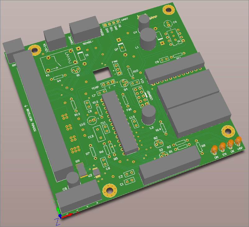
The designs were uploaded, I went on holiday and by the time I got back they were in my letterbox waiting for me. Let’s see how they look.
I think they’re looking great. No manufacturing flaws were expected because I wasn’t pushing any of the published limits and a quick once-over under a magnifying glass didn’t show up any problems. Time to assemble a board and do some testing.
Assembly
Assembling this board starts with the two surface mount parts, the INA226 and the current sense resistor. I tinned the pads with an iron and then reflowed the two parts in my reflow oven. It certainly felt like overkill for two parts but I have the oven so I use it whenever I can.
If you don’t have a reflow setup then it’s not difficult to do these two parts by hand with an iron if you have plenty of flux, good light and some hands-free magnification. There are many tutorials and videos on YouTube about how to hand-solder SMD parts.
After the two SMD parts are done it’s on to the simple but time-consuming task of bending, inserting, soldering and trimming the through-hole parts. It’s best to do these starting with the lowest profile resistors first and working up to the tallest parts. That way when you turn the board upside down to solder a part it will be held in place whilst you work by its own contact with your work surface.
Finally after a fairly long but strangely therapeutic soldering session it’s all done.
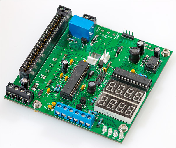
I know I’ve said it before but I do like the look of a project built with through-hole parts. It’s certainly a marvel to inspect a densely packed SMD board but the look of a through-hole project with all those chunky bits on it appeals more to me. Next I’ll insert the NXA66 into the edge connector and build up the temperature sensor cable.
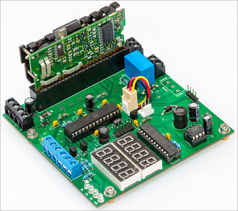
I made a cable for the temperature sensor out of a cheap 3-pin computer fan cable that I got on ebay. The connector on the other end was snipped off and the resulting wire ends were soldered to the MCP9700 TO-92 leads. The fan’s not fitted in these photographs. I’m still waiting for that to be delivered. Hopefully it’ll be ready by the time I shoot the video that’ll accompany this article.
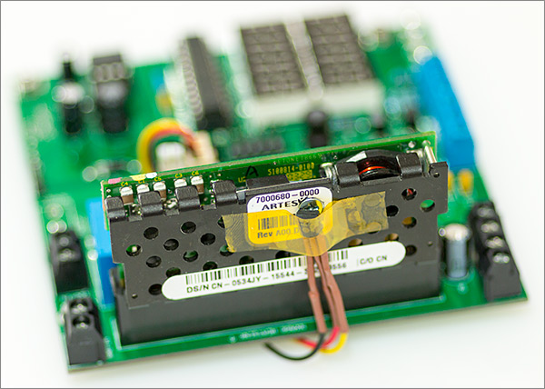
I used some heat-shrink tube to insulate the legs of the TO-92 and then kapton taped it to the back of the heatsink where I can see that it makes contact on the other side with the power MOSFET. This should be the hottest part of the heatsink and therefore the best place to take measurements.
The firmware
I connected up the 12V input to my bench PSU and switched on. The power LED came on which meant that the 5V regulator was working. Of course there was no output from the NXA66 because the relay that controls power to it was switched off. What I did next was to check that the AtMega328P would talk to me through the ISP header. It did, so now I’m good to go with writing the firmware.
The basic aims of the firmware are:
When the device is powered up it should restore its most recent settings from the onboard EEPROM. If the output enable switch is in the ‘on’ position then the output should be immediately enabled. This enables the device to continue where it left off in the event of an unexpected reboot or power outage.
The upper LED should show the voltage level reported by the INA226. The lower LED should show the current reported by the INA226.
There are two switches and a rotary encoder with an integrated button. Their functionality is as follows:
- The VSP switch should switch between 3.3V and whatever alternative voltage level is provided by the NXA66, either 5V or 2.5V.
- The output enable switch electronically disables the output.
Since the NXA66 does not like switching levels while the power is on we will use the relay to cut the power before setting the new level and switching the relay back on.
The rotary encoder and its integrated button will be used to navigate through a single-level menu of configuration options displayed on the upper display. Pressing the button will bring up the first menu item. Turning the knob will ‘scroll’ through the options. Pressing the button again will enter that menu option and then the knob can be used to adjust the configured value and the knob will confirm it and save the new value to EEPROM. Doing nothing for an idle time of 10 seconds will abort the menu process and go back to the main voltage/current display.
Rudimentary but intelligible letters can be displayed on the 4-digit LED display and that will be enough for me to provide the menu navigation. The configurable options will be:
- Calibration. The INA226 is configured with a calibration value for a perfect 2mΩ current sense resistor. In the real world the actual resistor value will be off by a small amount and this option will allow me to compensate for that. By applying a load and monitoring the current flow with an accurate instrument I will be able to change the calibration so my displayed current matches the instrument.
- Over-current protection. I will be able to program an upper-limit to the output current. If this limit is exceeded then the output will be automatically disabled. I’ll be doing this by monitoring the polled output from the INA226 so there will be a delayed response of a few hundred milliseconds — roughly the same as a slow-blow fuse.
- Data logging. I will periodically transmit the measured current and voltage values to the UART port. This option allows me to configure how often that happens, or disable it.
- LED brightness. A convenience feature to allow me to adjust the brightness of the LED displays.
- Fan activation levels. The fan can be configured to switch on when a certain temperature is exceeded and then switch off when the temperature falls back below a lower level. I’ll be able to customise those temperature levels with this option.
- Temperature display. There’s nowhere to continuously display the temperature so this option will allow me to check its current level.
It didn’t take long to write the firmware and I’m quite pleased with the result. It’s all open-source of course and you can view it here on github. In the bin directory you can find hex files that correspond to each release. These can be uploaded directly to the AtMega328p using the USBASP programmer.
avr-size nxa66.elf | tee nxa66.siz
   text    data     bss     dec     hex filename
   7486     180     191    7857    1eb1 nxa66.elf
Looking at the compiled size it appears that I could have fitted it into an AtMega8 but there’s no price advantage for me to do that since they both cost about the same in single units. That’s one thing I really like about the AVR 8-bit instruction set – the code density is so high that you get a lot of functionality into a small amount of flash. This firmware would have been at least double the size if implemented in the ARM 16-bit thumb instruction set.
The MCU operates on its internal 8MHz oscillator. The fuse values required for that are programmed using avrdude:
$ avrdude -c usbasp -p m328p -e -U lfuse:w:0xe2:m -U hfuse:w:0xde:mThe main loop of the firmware polls the INA226 every 200ms and updates the display. The configuration menu, if active, also runs in the main polling loop. Everything else runs asynchronously using interrupts:
- A 1Hz timer periodically triggers an asynchronous ADC conversion on the MCP9700 analog input. The ADC completion interrupt is used to read and convert the temperature reading. Click here to see how that’s done. Note that conversion to celsius is done with purely integer arithmetic – we don’t want to pull in bloated and slow floating point libraries just for this.
- The simple 8-bit Timer0 is used as a general purpose millisecond ticker. Click here to see how that’s done.
- The power good signal from the NXA66 is connected to the
INT0pin. When the pin changes state we get an interrupt and set the onboard LED accordingly. Click here to see the code for that. - The UART transmitter uses an interrupt to tell it when the transmit register is ready for data. We use this to send out our data logging strings without having to do a blocking poll on the register that holds the ‘ready’ flag. Click here to see the code.
Programming using interrupts can greatly increase the efficiency of your firmware, indeed many of my STM32 firmware implementations are entirely interrupt driven. That is, the main loop does absolutely nothing at all. Programming using interrupts does require additional care and attention though. Some of the most important that spring to mind are:
The volatile qualifier must be used on data that is to be shared with code executed in a different context. This will stop the compiler re-ordering instructions or caching writes that could mess things up. Don’t use volatile unless you need it though because it restricts the optimiser’s attempts to make you look good.
You cannot read or write a variable in the main loop that is accessed in an interrupt context if that variable is wider than the MCU can write in an atomic instruction. For the AVR that means you cannot share an int because it’s 16 bits wide and requires two instructions to write. An interrupt can occur between the two instructions and leave the variable in an incorrect state. To get around this on the AVR, either disable interrupts while a wide variable is accessed or use an 8-bit flag to indicate a ‘locked’ state.
Don’t spend ages in an interrupt service routine if other things could be held up by you. In an environment without hierarchical interrupts everything else is suspended and important interrupts such as those that keep time will not be running.
You will not be able to use functionality that depends on other interrupts being serviced. For example, polling a millisecond timer counter in an interrupt routine isn’t going to work because the code that updates the counter cannot run.
Testing
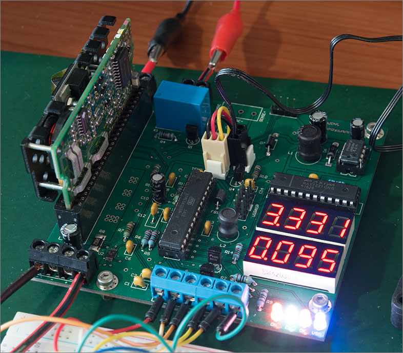
Writing the firmware steadily opened up each feature of the board and I was quickly able to sign off everything as working as designed. An advantage of using the MCU embedded in the Arduino is that there’s a lot of open source code out there to drive ICs and MCU peripherals. Not all of it is great, but even the low-quality code can give you a head start with the fundamentals of how to begin.
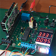
I was able to re-use a character font library for the MAX7221 and the popular ‘Wire’ library for driving the I2C peripheral that I needed to talk to the INA226. Here’s a picture of the device up and running, supplying 95mA to a test load.
I’m going to design a case for this power supply with switchgear and banana sockets on the front but until that comes I needed a quick hack to access the switches and the rotary encoder. I did this with a dremelled and drilled piece of stripboard that I could push the switches through and solder them to some access wires on the copper side.
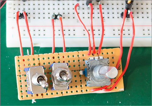
It’s a hack, and it’s had to be patched up once already but it has allowed me to get through this testing phase without a real case.
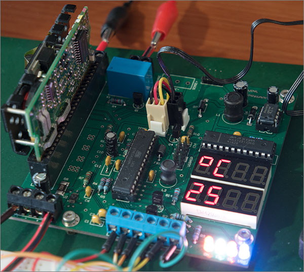
The temperature monitoring and dynamic fan control also seem to be working well. Here’s a snapshot of the configuration menu item that displays the current temperature.
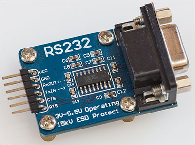
Now let’s take a look at the data logging. I hooked up the UART pins to one of those little adapter boards that you can get on ebay. The protocol is 19200-8-N-1.
This allowed me to connect a serial cable to the back of my PC and receive the logged data. Each line of data contains the millisecond timestamp of the sample, the voltage and current readings and the 8-bit CCITT CRC of all characters preceding the CRC number itself.
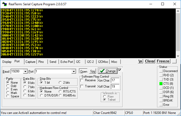
The default configuration transmits a new line once per second but this can be modified in the configuration menu.
Room for improvement
There’s always room to make improvements to a project. Here’s a couple of things that I noticed that could be improved.
- The board cutout is not large enough to allow a standard 3-pin fan plug to be threaded through it. I had to cut my fan lead and resolder it back together after plugging it in to the board.
- I forgot to add silkscreen pinout information for the UART header so you have to have the design open for reference when connecting up the UART.
Both of the above issues are fixed in the Gerber files that you can download from my site.
Video
If you’d like to see me try to make something as mundane as a power supply appear interesting in a video then you can do so by clicking below. Better resolution can be had by viewing the video on the main YouTube site.
Build your own
If you’d like to have a go at building one of these yourself then I’d certainly recommend it. If you’re confident you can solder the surface-mount INA226 then everything else is a walk in the park.
Click here to go to my downloads page where you will find a link to download the Gerber files in a form that you can directly upload to a site like PCBWay, Elecrow, ITead, Seeed etc. The board is a two layer 10x10cm design.
Click here to go to the Github repository for the firmware. In the bin directory you will find a compiled .hex file for each release. If you have avrdude installed then the firmware can be flashed and the fuses set with the following commands:
$ avrdude -c usbasp -p m328p -e -U flash:w:nxa66.hex
$ avrdude -c usbasp -p m328p -e -U lfuse:w:0xe2:m -U hfuse:w:0xde:m
Replace nxa66.hex with the name of the hex file that you downloaded.
Final words
It’s nice when something works first time and I’m pleased that this project was one of those. I now need to finish it off with a nice transparent acrylic laser cut case which means spending some hours in front of Inkscape. I’ll do that and be sure to write up my experience in another article here.
If you’d like to comment on anything in this article the please feel free to use the comments section below. If you have more detailed comments or questions then please use the forum and I’ll get back to you as soon as I can.