Tags
Related Posts
Share This
Recent Posts
Nokia QVGA TFT LCD for the Arduino Mega. Design and build (part 1 of 2)
In two of my previous articles I showed you how to reverse engineer the Nokia 2730 LCD for connecting to a device with 3.3V I/O’s and then I showed you how to build a 16-channel level converter for connecting devices together that have differing I/O level requirements.
This article brings together the knowledge we have gained in the previous two articles and puts it to use by creating a project that will allow a Nokia QVGA 24-bit colour TFT LCD to be indirectly connected to an Arduino Mega via a level converter, all on one small 50mm PCB.
All quite straightforward so far. The real innovation will be in the graphics library that I present in part two of this article set. The graphics library will use the external memory interface built in to the Arduino Mega to transfer data to the LCD in a single assembly instruction.
There is no faster way to transfer data out of the Arduino Mega to a peripheral. Doing it like this opens up the possibility of full colour bitmap graphics at a respectable refresh speed.
So now you know the endgame, let’s take the time to explain it all in detail.
The Nokia 6300 24-bit QVGA LCD
Perhaps the first surprise of this article is my choice of LCD. Given that the previous article showed how to reverse engineer the Nokia 2730 LCD you could have been forgiven for assuming that this was the one I’d use.
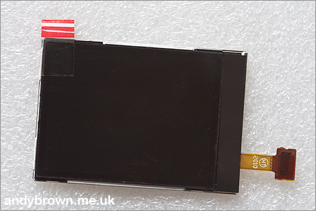
The 6300 panel with protective film attached
Well, since that project I noticed that a great many of Nokia’s QVGA displays seem to vary only slightly in their pinouts and as such the likelihood of them using the same controller would be high. I picked the Nokia 6300 for this project for the following reasons:
- It’s readily available (on ebay) and costs very little.
- It claims to support 16M colours (24 bit). You would be forgiven for not noticing the difference between 16M and 262K colours though.
- It’s pin compatible with a large number of Nokia models: 6300, 6301, 5310, 7500, 8600, 6120C, E90 and E51.
- The connector is readily available from online sources.
The connector
The connector is the same 24-pin board-to-board connector used in the Nokia 2730. An eagle-eyed reader has identified the manufacturer and the part number. It is made by JST and the part number is 24R-JANK-GSAN-TF. Here’s the datasheet.
It is easy to obtain them either direct from JST’s online shop or in small quantities from online sources. Here are some direct links to the ones that I know of:
The pinout for the connector is shown here:

Here’s a photograph of the LCD side of the connector. If you look closely you can see where the ground pins connect directly into the ‘ground pour’ inside the ribbon cable. This helps to identify where pin 1 is located because the big “1” silkscreen’d on to the FPC is in the wrong place.
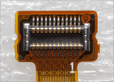
The connector on the LCD FPC cable
The backlight
Like the 2730 before it, the 6300 backlight consists of 4 white LEDs in series requiring around 13V to power them. Just like before, I will use the OnSemi NCP5007 constant current backlight driver to do the heavy lifting here.
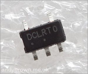
The NCP5007 in SOT23-5 package
The NCP5007 will be configured to supply a constant 20mA through the backlight circuit and we will use a PWM signal on the ENABLE pin to vary the brightness.
Power supply design
We need both 5V and 3.3V inputs for this design. 5V will be used to power the backlight driver as well as set the reference level for the Arduino side of the level converter. 3.3V will be used to set the reference for the LCD side of the regulator.
The backlight draws the most power from this design so I will optionally allow 5V to be supplied externally from a supply that shares a common ground with the Arduino itself.
TFTs like these draw a very small amount of current, typically less than 10mA so I will supply it indirectly from a GPIO pin through the level converter. This allows me to control the order in which power is applied. Many TFTs prefer their I/O supply to come up before the panel supply and for safety I’m going to assume that this is the case with this device. Had the device required significant amounts of current I would have had to use a couple of transistors to switch the current on and off.
Arduino interface design
The Nokia 6300, like the Nokia 2730, uses an 8-bit 8080 protocol to communicate with the LCD. The 8080 protocol consists of a chip select signal, 8 bits of data, read and write lines and another line that is used to indicate whether you want to transfer data or set a command register value.
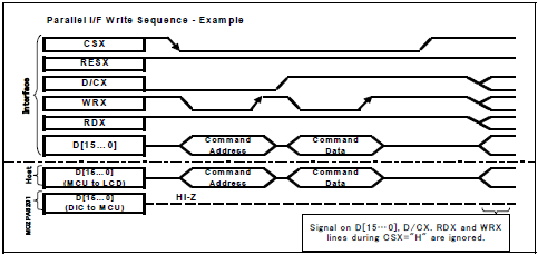
The 8080 protocol write cycle
The above image summarises the state of the 8080 bus during a write cycle. The key point to note is that data is transferred to the controller on the rising edge of the WR line. Can we get this line from the Arduino Mega’s external memory interface? Well yes, we can. The following diagram from the datasheet shows the timing of the external memory bus.
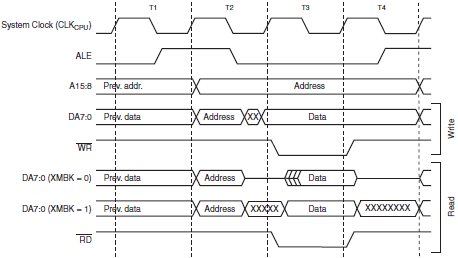
The ATMega1280 external memory timing
Note the behaviour of the address latch enable (ALE) line. We need an active-low chip select (/CS) signal that is low during the data setup and transfer phase. ALE behaves perfectly in this respect and we will use it for chip-select. This is a critical part of the design. If ALE was not present or did not obey the above timings then this design would fail.
The register/data select line
This is the line used to select whether you’re transferring data or writing to a register. It is somewhat confusing in that it is variously referred to as RS or D/CX depending on which datasheet you’re reading. I’m going to call it RS from now on.
The trick we will use to select or deselect RS is one that we’ve been using on more powerful ARM MCUs for a long time. We will attach RS to external address line A8. That means that if we write to a memory location that has bit 8 set in its address then we will transfer 8 bits with RS high. Conversely if we write to a memory location that has bit 8 reset in its address then we will transfer 8 bits with RS low. A neat trick!
The only precaution that we must take is that we select an address that is not actually in the internal 8Kb SRAM, the address must be up above that range to avoid a clash. We will use address 0x8000 for writing to a register (RS=low) and address 0x8100 for writing data (RS=high).
Selecting a low address line (A8) means that we can free up address lines 10 to 15 for GPIO, saving 6 pins. It doesn’t matter that our selected address locations 0x8000 and 0x8100 are high up in the address range who’s address lines are free’d for GPIO. The ATMega will still correctly control A8. Not only is this design fast, it’s frugal with pins too. Here is the mapping of Arduino pins to their LCD function.
| Arduino | ATMega Port | Function |
|---|---|---|
| 22 | PA0 | D0 |
| 23 | PA1 | D1 |
| 24 | PA2 | D2 |
| 25 | PA3 | D3 |
| 26 | PA4 | D4 |
| 27 | PA5 | D5 |
| 28 | PA6 | D6 |
| 29 | PA7 | D7 |
| 34 | PC3 | VIO |
| 35 | PC2 | VDD |
| 36 | PC1 | A9 (1) |
| 37 | PC0 | RS |
| 38 | PD7 | /RESET |
| 39 | PG2 | /CS |
| 40 | PG1 | /RD (2) |
| 41 | PG0 | /WR |
(1) A9 is not used but cannot be released for GPIO.
(2) /RD is not used but cannot be released for GPIO and is pulled up to VIO.
Our design is write-only to the LCD. We cannot read data back from it, and would never want to.
The schematic
Now that we have a design we can create the schematic in the Eagle designer. All the 5V signals from the Arduino that are destined for the LCD are routed through the level converter and will come out the other side at 3.3V.

The schematic (click for larger PDF)
Parts list
Here’s a list of the parts that I used for this build.
| Part | Value | Device | Package |
|---|---|---|---|
| C-6300 | NOKIA12X2 | 24R-JANK-GSAN-TF | 12X2 |
| C1 | 4.7u | ceramic | 0805 |
| C2 | 1u | ceramic 50V | 0805 |
| C3,C4,C6,C7,C8,C9 | 100n | ceramic | 0603 |
| C5 | 4.7u | ceramic | 0805 |
| D1 | CD214A-B140LF | schottky | DO214AC |
| L1 | 22uH | LQH3NP_J0 | 1212 |
| MEGA | pin header | MA12-2 | MA12-2 |
| R1 | 10R | resistor | R0805 |
| R3 | 33K | resistor | R0805 |
| SV2 | pin header | MA03-2 | MA03-2 |
| U1 | NCP5007 | NCP5007 | SOT23-5 |
| U2 | 74ALVC164245DLSTD | 74ALVC164245DLSTD | SSOP48DL |
The board
After creating the schematic the next stage is to switch to the CAD designer and lay out the board. I placed the components and routed the traces manually. The connector is placed so that the FPC will wrap around the board edge and allow me to mount the LCD on the other side using double-sided sticky tabs.
With the LCD facing up, the interface pins face down and press directly into the sockets on the Arduino. The pin header is placed as close to the edge of the board as possible so that adjacent Arduino pins are not obscured.
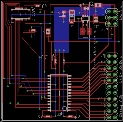
The PCB layout and routing
After staring at the layout until I’m square-eyed (sound familiar to anyone?) I’m feeling confident that the header pins are all where they should be, the connector positioning will result in the LCD ending up in the right place and the silk-screening will end up on the correct side of the board.
The build
With the board design complete I uploaded it to ITead Studio for manufacturing. About two weeks later the boards arrived in the mail. As usual all were perfectly manufactured with no visible flaws.
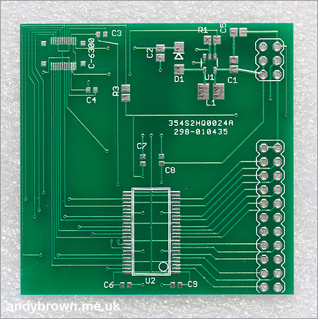
The component side of the board
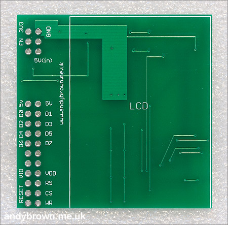
The LCD side of the board
I construct the boards by tinning the pads and then reflowing the larger components such as the level converter, LCD connector socket and the NCP5007 using a hot-plate. I then reflow the smaller discrete components using my Aoyue hot-air gun.
After the completed PCB is cleaned and dried the design is completed by pressing the LCD connector into its socket and mounting the panel on double-sided sticky pads. That it fits comfortably on to the pads was a bit of a relief because the metal back of the panel must stand clear of the traces and particularly the vias on that side of the board.
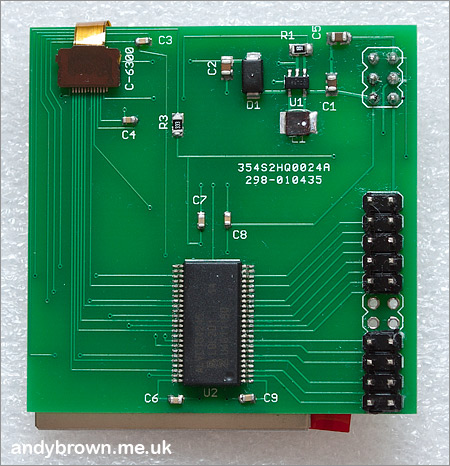
The component side of the board
The open holes in between the groups of header pins allow the unused Arduino pins to be accessed for general purpose use. The designers of the Arduino clearly knew what they were doing when they grouped together the external memory pins in the same place.
Unfortunately as you free up unused address pins from A15 downwards they free up from the middle of the external memory pin group. It would have been a nice design touch if they’d free’d from the end of the group instead but you can’t have everything.
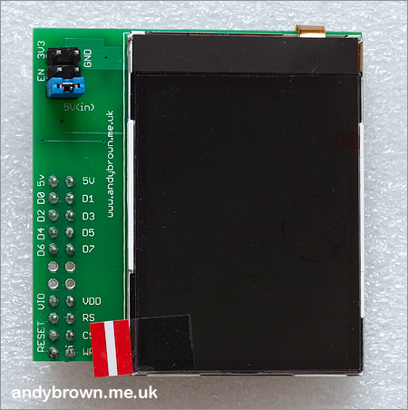
The LCD side of the board
It fits perfectly, and it should do because I did carefully measure everything first. However you never really know if you’ve got it right until the hardware arrives and you put it all together.
It is required to connect the 3.3V and GND pins to the Arduino. With the blue jumper connected 5V will be taken directly from the Arduino board and used to power the backlight. With the jumper disconnected I must supply a regulated 5V myself to the 5V (in) pin.
If I want to control the backlight brightness using a PWM signal then I can connect that signal to the EN pin. Alternatively I can jumper the EN pin across and that will tie it high meaning that the backlight will always be at 100% brightness.
The software library
Now that the build is complete we need a software graphics library to exploit the capabilities of our new hardware. Continue reading part two of this two part series of articles where I present an advanced, high performance graphics library with lots of examples to try out and videos to watch.
Update: 2 July 2012
I have noted that not all boards obtained on ebay are the same. To my surprise there are slight differences in the behaviour, nothing radical but enough for me to justify a new release of the software driver to deal with this ‘type B’ model. I will refer to the original model as ‘type A’.
The differences found so far are:
- Type B will not initialise using my 16M driver. They require the 262K driver and then they will look and behave the same as before.
- The hardware scrolling offset is reversed. Type ‘A’ boards scroll up one line with an offset of 319. These type ‘B’ boards will scroll up one line with an offset of 1.
- Type ‘B’ boards support the faster 64K driver. Type ‘A’ boards do not. The raw fill rate for the 64K colour mode is 1.32 megapixels/second. It is 1.06 megapixels/second for the 262K and 16M modes on both boards.
- These type ‘B’ boards seem to have a brighter backlight and could probably run optimally on a 90% PWM duty cycle.
There will be a software update in the next few days (now released, version 1.1.0) to support the difference in hardware scrolling behaviour.
Update: 23 September 2012
Another controller variant has turned up and we’re going to call this one ‘Type C’. It’s showing up in both 6300 and N82 screens. It behaves the same as Type A screens except for the following differences:
- It won’t go into BGR colour transfer mode, only RGB is supported. Since RGB is supported by all variants I’ve seen RGB will become the default mode in my driver code from 2.2.0 onwards.
- Page and column addresses are not reversed in landscape mode.
Type C panels are supported from version 2.2.0 of my driver code using a _TypeC suffix to the driver name. e.g. Nokia6300_Landscape_262K_TypeC.
Schematics, CAD and gerbers available
I have open-sourced my PCB design and CAD files so if you’re interested in building your own boards then head on over to my downloads page and grab yourself a copy. The archive includes gerbers for both the SSOP-48 and TSOP-48 level converter footprints.


