


A generic optimised 16-bit LCD adaptor for the Arduino
There are many TFT modules available on the market that are designed to connect directly to an MCU to provide a full colour graphical display, just search ebay for “tft module” to see what I mean.
Unfortunately for Arduino users the majority of these modules expose a 16-bit interface and are designed to be connected to ARM devices. The way I see it there are two problems to be solved here in order to allow them to be connected to an Arduino. Firstly, they are always designed to be run at 3.3V and secondly the 16-bit data bus uses up a ton of GPIO pins.
I’m going to present a combination of hardware and software that solves both of those problems and also shows how you can achieve extremely high performance with a few driver optimisation tricks.
The hardware adaptor
I decided to design an adaptor that would feature 5V to 3.3V level conversion as well as a latch that would allow me to reduce the pins required by the data bus from 16 to 8 at the expense of an additional pin for controlling the latch. A total saving of 7 pins over the simplistic solution.
How does the latch work?
The latch works sort of like a small memory. In ‘transparent’ mode signals pass right through it and come straight out the other side. When you flip to ‘latched’ mode the latch ignores its inputs and continues to output the last values it received on those inputs.
I can use these properties of the latch to push out two 8-bit values in sequence and have the latch ‘expand’ them to 16-bits.
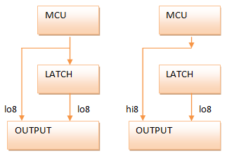
The diagram shows the two phases of the operation of the latch. In the first phase I push out the low 8-bits which gets routed through and around the latch to occupy both the low (which I want) and the high (which I don’t want) bytes of the output. In the second phase I lock the latch and then push out the high 8-bits. The latch ignores this new data and so the only route is around the latch into the correct position in the outputs.
Another advantage of the latched design is that it dovetails nicely with the external memory (XMEM) peripheral that comes built in to the Arduino Mega 1280 and 2560. With a little bit of clever code I should be able to use the XMEM interface to drive the LCDs.
The schematic
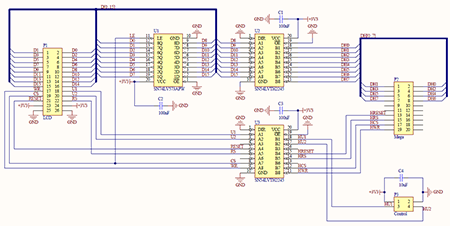
Click the image to download a PDF
The schematic pulls together the level conversion, latch, a connector designed to directly fit the Arduino Mega and an output connector for the 16-bit LCD. I’ll explain each sub-section of the schematic here.
The Arduino Mega Connector
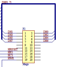
This a 10×2 male pin header with pin assigments designed to match the Arduino Mega’s XMEM interface that is exposed in the block of pins starting at 23. The letter ‘H’ in the net designators indicates that these are high level 5V signals. I should probably have used ‘T’ for TTL but there you go.
The data and control signals are all there, including CS (chip-select) that I map to ALE (address latch enable) on the XMEM interface even though this signal is rarely required by the LCD panels and can usually be just tied to ground.
The level converters
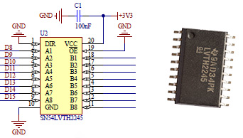
The SN54LVTH2245 octal bus transceiver from Texas Instruments is an ideal choice for level conversion in this design. The propagation delay at 3.3V is around 2ns which is very fast. The inputs and outputs are on opposite sides of the package which simplifies routing and it’s easy to find the device on the market.
The latch
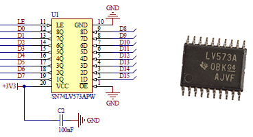
The SN74LV573APW transparent D-Type latch, again from Texas Instruments, satisfies the speed requirements imposed by the XMEM interface and is easy to find on the market. Latches, like bus transceivers are readily available in all shapes and sizes and there’s nothing to stop you using different parts as long as the specifications are similar to these.
The control header
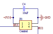
This is a 2×2 pin male header that I’ll use to provide the vital power and ground supplies from the Arduino board. The two ‘user’ inputs U1 and U2 can be used to convert any arbitrary output signal from the Arduino from 5V down to 3.3V. I added these because I had some unused ports on the level converters and it did seem a shame to waste them. Later on you will see how I use one of these to provide a PWM backlight control to the LCD panels.
The output connector
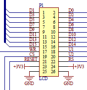
This connector provides the output signals for the LCD. In my design I’ll be using a right-angled male header to simplify the rats nest of interconnecting wires that need to be connected here.
As well as the output signals there are pairs of power and ground outputs. You can’t have too many of those!
Bill of materials
Here’s a table showing the full bill of materials (BOM) for this design.
| Description | Designator | Footprint |
|---|---|---|
| Ceramic capacitor, 100nF | C1, C2, C3 | 0603 |
| Ceramic capacitor, 10µF | C4 | 0805 |
| Header, 13×2, right angle | P1 | HDR2X13H |
| Header, 10×2 | P2 | HDR2X10 |
| Header, 2×2 | P3 | HDR2X2 |
| SN74LV573APW transparent D-Type latch | U1 | TSOP-20 |
| SN54LVTH2245 octal bus transceiver | U2, U3 | SOIC-20 |
The PCB design
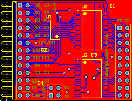
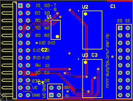
Click images for PDFs
Manually routing the board didn’t present any real challenges and I was able to fit the whole design into a 45mm by 35mm PCB. Thankfully this time I’d remembered to check that the level converters had inputs and outputs on opposing sides of the package instead of adjacent to each other.
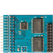
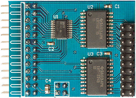
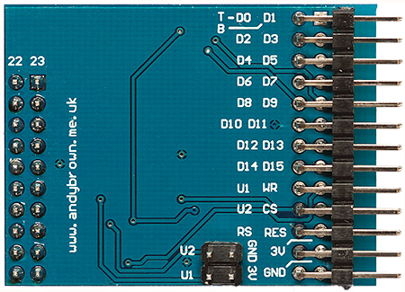
Building the board
Once the PCB layout was finalised and the Gerber CAM files exported I then uploaded them to ITead Studio’s manufacturing service and waited the requisite 2-3 weeks for them to arrive in the post.
![]()
![]()
As usual the quality is spot-on with no defects evident at all. This time I went with a blue solder mask so that it would match the PCB colour of the Arduino Mega that it’s designed to slot into.
Now it’s time to build it.
My procedure for building a PCB with surface mount components remains unchanged. Firstly I tin all the pads with a soldering iron and some highly active flux that makes for easy drag soldering across the small IC pads. Then I thoroughly clean all the flux residue off the board because the acids can attack the board over the long term.
Now the pads are tinned I use a hot-plate to reflow the ICs into place and touch up the reflowed joints afterwards under a binocular microscope. The discrete components are then reflowed into place with my Aoyue 852A hot air gun and finally the pin headers are soldered into place with an ordinary soldering iron. The final touch is to wash the boards in hot soapy water and leave to dry for 24 hours.
Now I’ve got something that I can play with it’s time to see if I can come up with some driver software that will do it justice. Something tells me I can…
The software drivers
My previous Nokia QVGA reverse engineering efforts that you can find documented extensively on this site have left me with a flexible and expandable driver that will make a good base from which to add support for this new adaptor.
The driver code is separated into access modes and panel drivers that are bound together with a graphics library at compile-time by using C++ templates. To support this new adaptor I will need to write at least one new access mode and as many panel drivers as are required to support the panels that I own.
Let’s get started by taking a look at the 16-bit XMEM access mode.
The 16-bit xmem access mode
The XMEM interface built into the Arduino Mega MCU is designed to provide access to external memories with a 16-bit address bus and an 8-bit data bus. It just so happens that the protocol for accessing these memories is close enough to the 8080 protocol required by the LCDs that I can sometimes use it successfully. I say ‘sometimes’ because external factors such as the panel timing parameters do come into play.
So, when the Arduino Mega wants to write to an external memory it does the following:
- ALE is driven high.
- It drives the 16-bit address on to the bus where the lower 8 bits are multiplexed with the data lines.
- ALE is driven low, locking in the lower 8-bits of the address.
- It pules the WR line from high to low and to high again. Data is transferred on the rising edge of the pulse.
I can make use of this sequence to transfer 16-bits to the LCD in a single transaction that also includes the RS (register/data select) line. I will use the lower 8-bits of the 16-bit address to transfer the lower 8-bits of LCD data. I will use address line A8 to hold the RS signal and I’ll use the 8 data lines to transfer the upper 8-bits of LCD data. I will also set bit 15 of the address so that I’m guaranteed to be in the external memory range and will not collide with the internal 8Kb of SRAM.
Let’s take a look at the pinout for this access mode:
| Arduino | Port | Function |
|---|---|---|
| 22 | PA0 | D0/D8 |
| 23 | PA1 | D1/D9 |
| 24 | PA2 | D2/D10 |
| 25 | PA3 | D3/D11 |
| 26 | PA4 | D4/D12 |
| 27 | PA5 | D5/D13 |
| 28 | PA6 | D6/D14 |
| 29 | PA7 | D7/D15 |
| 35 | PC2 | /RESET |
| 37 | PC0 | RS |
| 39 | PG2 | /CS |
| 41 | PG0 | /WR |
Initialising the XMEM interface is a simple matter of writing the correct values to the two XMEM registers. The XMEM pins 30..34 (PC3..PC7) are free’d up for GPIO.
inline void Xmem16AccessMode::initialise() {

  // set up the reset pin
  pinMode(RESET_PIN,OUTPUT);
  digitalWrite(RESET_PIN,HIGH);

  // set up the xmem registers

  // free PC3..PC7 for user GPIO
  XMCRB=_BV(XMM1) | _BV(XMM2);

  // enable xmem, no wait states
  XMCRA=_BV(SRE);
}
Because performance is absolutely paramount I wrote the data and command output functions in AVR assembly language.
inline void Xmem16AccessMode::writeData(uint8_t lo8,uint8_t hi8) {

  // this is equivalent to:
  // *reinterpret_cast<volatile uint8_t *>(0x8100 | lo8)=hi8;
  // this method costs 5 clock cycles

  __asm volatile("  ldi r27,0x81  \n\t"
                 "  mov r26,%0    \n\t"
                 "  st  X,%1      \n\t"
                 :: "d" (lo8), "d" (hi8)
                 : "r26", "r27");
}
In AVR assembly language the combination of r26 and r27 make up a 16-bit X register that we use in the above code to send the 8-bit data value to the external memory. It’s also helpful that r26 and r27 are free for use in inline assembly code without fear of colliding with code emitted by the C++ compiler. Nevertheless I do declare them in the ‘clobber’ list at the end of the __asm section.
The method used to write a command is almost the same, except bit A9 is set to zero:
inline void Xmem16AccessMode::writeCommand(uint8_t lo8,uint8_t hi8) {

  // this is equivalent to:
  // *reinterpret_cast<volatile uint8_t *>(0x8000 | lo8)=hi8;
  // this method costs 5 clock cycles

  __asm volatile("  ldi r27,0x80  \n\t"
                 "  mov r26,%0    \n\t"
                 "  st  X,%1      \n\t"
                 :: "d" (lo8), "d" (hi8)
                 : "r26", "r27");
}
To see this access mode in action we need a logic analyser so I hooked up the output of the adaptor to my Ant18e and captured the lower 8 data lines, RS and WR.
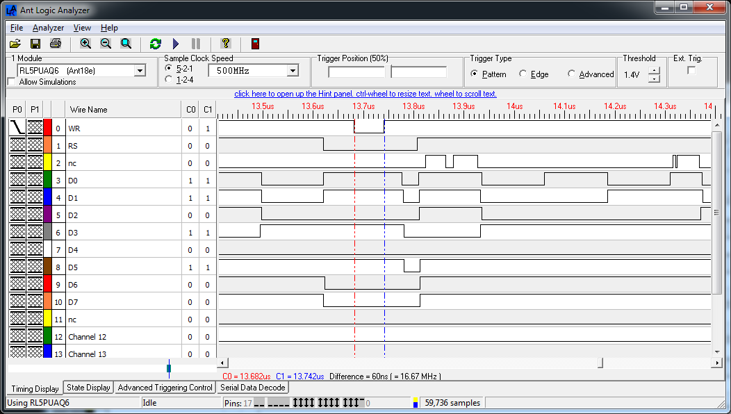
Click for larger
I can see from the section between the two timing markers that the AVR core pulses WR for exactly one clock cycle.
Some of the panels that I have are not happy with the tight timings provided by the XMEM interface, even when I add some address and data hold cycles so for this reason I decided to branch out and build an optimised GPIO access mode. I’m glad that I did because in some areas the optimisations that I created resulted in a huge performance increase.
The 16-bit gpio access mode
The 16-bit GPIO access mode emulates the automatic operation of the XMEM interface by using ordinary GPIO. There are advantages and disadvantages to this approach. Single writes are going to be a few cycles slower than the XMEM interface but for multiple writes of the same value I can optimise heavily to create a routine that will outperform anything else as long as the panel supports 16-bit (64K colour) mode. The other advantage is that I’m not restricted to the XMEM pins and I could even get it to work on the ordinary 32Kb Arduino.
Gpio16LatchAccessMode is a template that takes a type containing my port and pin mappings as its parameter. For example, using the same ports and pins as Xmem16AccessMode I declare this type:
struct Gpio16LatchAccessModeXmemMapping {
  enum {

    // ports are the I/O index, not the physical address

    PORT_DATA  = 0x02,    // PORTA
    PORT_WR    = 0x14,    // PORTG
    PORT_RS    = 0x08,    // PORTC
    PORT_ALE   = 0x14,    // PORTG
    PORT_RESET = 0x08,    // PORTC

    // pins are the 0..7 port index, not the arduino numbers

    PIN_WR    = PIN0,
    PIN_RS    = PIN0,
    PIN_ALE   = PIN2,
    PIN_RESET = PIN2
  };
};
The Gpio16LatchAccessMode template looks like this. You can see that I also provide a concrete instantiation of the template using a typedef for easy use.
template<typename TPinMappings>
class Gpio16LatchAccessMode {

  protected:
    static uint8_t _streamIndex;
    static void initOutputHigh(uint8_t port,uint8_t pin);

  public:
    static void initialise();
    static void hardReset();

    static void writeCommand(uint8_t lo8,uint8_t hi8=0);
    static void writeCommandData(uint8_t cmd,uint8_t data);
    static void writeData(uint8_t lo8,uint8_t hi8=0);
    static void writeMultiData(uint32_t howMuch,uint8_t lo8,uint8_t hi8=0);
    static void writeStreamedData(uint8_t data);
};

typedef Gpio16LatchAccessMode<Gpio16LatchAccessModeXmemMapping> DefaultMegaGpio16LatchAccessMode;
I’ll skip the initialise method because I’m sure you’re not particularly interested in code that just sets the direction and level of GPIO pins. Let’s get straight on to the writeData() and particularly the writeMultiData() methods. Firstly, writeData(), the method that writes out a single value:
template<class TPinMappings>
inline void Gpio16LatchAccessMode<TPinMappings>::writeData(uint8_t lo8,uint8_t hi8) {

  __asm volatile(
      "  sbi %1, %5   \n\t"     // ALE   = HIGH
      "  out %3, %7   \n\t"     // PORTA = lo8
      "  sbi %2, %6   \n\t"     // RS    = HIGH
      "  cbi %1, %5   \n\t"     // ALE   = LOW
      "  out %3, %8   \n\t"     // PORTA = hi8
      "  cbi %0, %6   \n\t"     // /WR   = LOW
      "  sbi %0, %6   \n\t"     // /WR   = HIGH

      :: "I" (TPinMappings::PORT_WR),     // %0
         "I" (TPinMappings::PORT_ALE),    // %1
         "I" (TPinMappings::PORT_RS),     // %2
         "I" (TPinMappings::PORT_DATA),   // %3
         "I" (TPinMappings::PIN_WR),      // %4
         "I" (TPinMappings::PIN_ALE),     // %5
         "I" (TPinMappings::PIN_RS),      // %6
         "d" (lo8),                       // %7
         "d" (hi8)                        // %8
        );
}
Straightforward stuff. We just bit-bang the 8080 protocol with the additional overhead of the latch programming.
Now, it’s very common in graphics libraries to write out solid blocks of colour. Whether you’re clearing the screen, drawing rectangles or just straight lines it all comes down to setting an ‘output window’ on the display and then pumping out pixels.
The writeMultiData() method takes advantage of the fact that you only need to set the data and RS lines once and then you can toggle the /WR line as often as you need to in order to write out your block of pixels. This technique was first suggested to me by Andrew, the author of this instructable. Here’s my take on the method.
template<class TPinMappings>
inline void Gpio16LatchAccessMode<TPinMappings>::writeMultiData(uint32_t howMuch,uint8_t lo8,uint8_t hi8) {

  __asm volatile(
    "    sbi  %9, %7       \n\t"      // ALE   = HIGH
    "    out  %1, %2       \n\t"      // PORTA = lo8
    "    sbi  %3, %8       \n\t"      // RS    = HIGH
    "    cbi  %9, %7       \n\t"      // ALE   = LOW
    "    out  %1, %4       \n\t"      // PORTA = hi8

    "    clr  r20          \n\t"      // r20 = global interrupt status
    "    brid intdis%=     \n\t"      // branch if global interrupts are off
    "    cli               \n\t"      // disable global interrupts (because we cannot let PORTG get modified by an IRQ)
    "    inc  r20          \n\t"      // r20 (global interrupts disabled) = 1
    "intdis%=:             \n\t"
    "    in   r18, %0      \n\t"      // get PORT_WR to r18 and r19
    "    mov  r19, r18     \n\t"
    "    cbr  r18, %6      \n\t"      // clear WR in r18
    "    sbr  r19, %6      \n\t"      // set WR in r19
    "    cpi  %A5, 40      \n\t"      // if howMuch<40 then jump to lastlot
    "    cpc  %B5, r1      \n\t"
    "    cpc  %C5, r1      \n\t"
    "    brsh batchloop%=  \n\t"
    "    rjmp lastlot%=    \n\t"
    "batchloop%=:          \n\t"
    "    out  %0,  r18     \n\t"      // toggle /WR 40 times
    "    out  %0,  r19     \n\t"
    "    out  %0,  r18     \n\t"
    "    out  %0,  r19     \n\t"
    "    out  %0,  r18     \n\t"
    "    out  %0,  r19     \n\t"
    "    out  %0,  r18     \n\t"
    "    out  %0,  r19     \n\t"
    "    out  %0,  r18     \n\t"
    "    out  %0,  r19     \n\t"
    "    out  %0,  r18     \n\t"
    "    out  %0,  r19     \n\t"
    "    out  %0,  r18     \n\t"
    "    out  %0,  r19     \n\t"
    "    out  %0,  r18     \n\t"
    "    out  %0,  r19     \n\t"
    "    out  %0,  r18     \n\t"
    "    out  %0,  r19     \n\t"
    "    out  %0,  r18     \n\t"
    "    out  %0,  r19     \n\t"
    "    out  %0,  r18     \n\t"
    "    out  %0,  r19     \n\t"
    "    out  %0,  r18     \n\t"
    "    out  %0,  r19     \n\t"
    "    out  %0,  r18     \n\t"
    "    out  %0,  r19     \n\t"
    "    out  %0,  r18     \n\t"
    "    out  %0,  r19     \n\t"
    "    out  %0,  r18     \n\t"
    "    out  %0,  r19     \n\t"
    "    out  %0,  r18     \n\t"
    "    out  %0,  r19     \n\t"
    "    out  %0,  r18     \n\t"
    "    out  %0,  r19     \n\t"
    "    out  %0,  r18     \n\t"
    "    out  %0,  r19     \n\t"
    "    out  %0,  r18     \n\t"
    "    out  %0,  r19     \n\t"
    "    out  %0,  r18     \n\t"
    "    out  %0,  r19     \n\t"
    "    out  %0,  r18     \n\t"
    "    out  %0,  r19     \n\t"
    "    out  %0,  r18     \n\t"
    "    out  %0,  r19     \n\t"
    "    out  %0,  r18     \n\t"
    "    out  %0,  r19     \n\t"
    "    out  %0,  r18     \n\t"
    "    out  %0,  r19     \n\t"
    "    out  %0,  r18     \n\t"
    "    out  %0,  r19     \n\t"
    "    out  %0,  r18     \n\t"
    "    out  %0,  r19     \n\t"
    "    out  %0,  r18     \n\t"
    "    out  %0,  r19     \n\t"
    "    out  %0,  r18     \n\t"
    "    out  %0,  r19     \n\t"
    "    out  %0,  r18     \n\t"
    "    out  %0,  r19     \n\t"
    "    out  %0,  r18     \n\t"
    "    out  %0,  r19     \n\t"
    "    out  %0,  r18     \n\t"
    "    out  %0,  r19     \n\t"
    "    out  %0,  r18     \n\t"
    "    out  %0,  r19     \n\t"
    "    out  %0,  r18     \n\t"
    "    out  %0,  r19     \n\t"
    "    out  %0,  r18     \n\t"
    "    out  %0,  r19     \n\t"
    "    out  %0,  r18     \n\t"
    "    out  %0,  r19     \n\t"
    "    out  %0,  r18     \n\t"
    "    out  %0,  r19     \n\t"
    "    out  %0,  r18     \n\t"
    "    out  %0,  r19     \n\t"
    "    out  %0,  r18     \n\t"
    "    out  %0,  r19     \n\t"
    "    out  %0,  r18     \n\t"
    "    out  %0,  r19     \n\t"
    "    out  %0,  r18     \n\t"
    "    out  %0,  r19     \n\t"
    "    subi %A5, 40      \n\t"        // subtract 40 from howMuch
    "    sbci %B5, 0       \n\t"
    "    sbci %C5, 0       \n\t"
    "    cpi  %A5, 40      \n\t"        // if howMuch >= 40 then go back for another batch
    "    cpc  %B5, r1      \n\t"
    "    cpc  %C5, r1      \n\t"
    "    brlo lastlot%=    \n\t"
    "    rjmp batchloop%=  \n\t"
    "lastlot%=:            \n\t"        // load index Z with the address of the end
    "    ldi  r31, pm_hi8(finished%=)   \n\t"
    "    ldi  r30, pm_lo8(finished%=)   \n\t"
    "    lsl  %A5          \n\t"        // multiply remaining by 2
    "    sub  r30, %A5     \n\t"        // subtract remaining*2 from Z
    "    sbci r31, 0       \n\t"
    "    ijmp              \n\t"        // jump to Z to finish off the writing
    "    out  %0,  r18     \n\t"
    "    out  %0,  r19     \n\t"
    "    out  %0,  r18     \n\t"
    "    out  %0,  r19     \n\t"
    "    out  %0,  r18     \n\t"
    "    out  %0,  r19     \n\t"
    "    out  %0,  r18     \n\t"
    "    out  %0,  r19     \n\t"
    "    out  %0,  r18     \n\t"
    "    out  %0,  r19     \n\t"
    "    out  %0,  r18     \n\t"
    "    out  %0,  r19     \n\t"
    "    out  %0,  r18     \n\t"
    "    out  %0,  r19     \n\t"
    "    out  %0,  r18     \n\t"
    "    out  %0,  r19     \n\t"
    "    out  %0,  r18     \n\t"
    "    out  %0,  r19     \n\t"
    "    out  %0,  r18     \n\t"
    "    out  %0,  r19     \n\t"
    "    out  %0,  r18     \n\t"
    "    out  %0,  r19     \n\t"
    "    out  %0,  r18     \n\t"
    "    out  %0,  r19     \n\t"
    "    out  %0,  r18     \n\t"
    "    out  %0,  r19     \n\t"
    "    out  %0,  r18     \n\t"
    "    out  %0,  r19     \n\t"
    "    out  %0,  r18     \n\t"
    "    out  %0,  r19     \n\t"
    "    out  %0,  r18     \n\t"
    "    out  %0,  r19     \n\t"
    "    out  %0,  r18     \n\t"
    "    out  %0,  r19     \n\t"
    "    out  %0,  r18     \n\t"
    "    out  %0,  r19     \n\t"
    "    out  %0,  r18     \n\t"
    "    out  %0,  r19     \n\t"
    "    out  %0,  r18     \n\t"
    "    out  %0,  r19     \n\t"
    "    out  %0,  r18     \n\t"
    "    out  %0,  r19     \n\t"
    "    out  %0,  r18     \n\t"
    "    out  %0,  r19     \n\t"
    "    out  %0,  r18     \n\t"
    "    out  %0,  r19     \n\t"
    "    out  %0,  r18     \n\t"
    "    out  %0,  r19     \n\t"
    "    out  %0,  r18     \n\t"
    "    out  %0,  r19     \n\t"
    "    out  %0,  r18     \n\t"
    "    out  %0,  r19     \n\t"
    "    out  %0,  r18     \n\t"
    "    out  %0,  r19     \n\t"
    "    out  %0,  r18     \n\t"
    "    out  %0,  r19     \n\t"
    "    out  %0,  r18     \n\t"
    "    out  %0,  r19     \n\t"
    "    out  %0,  r18     \n\t"
    "    out  %0,  r19     \n\t"
    "    out  %0,  r18     \n\t"
    "    out  %0,  r19     \n\t"
    "    out  %0,  r18     \n\t"
    "    out  %0,  r19     \n\t"
    "    out  %0,  r18     \n\t"
    "    out  %0,  r19     \n\t"
    "    out  %0,  r18     \n\t"
    "    out  %0,  r19     \n\t"
    "    out  %0,  r18     \n\t"
    "    out  %0,  r19     \n\t"
    "    out  %0,  r18     \n\t"
    "    out  %0,  r19     \n\t"
    "    out  %0,  r18     \n\t"
    "    out  %0,  r19     \n\t"
    "    out  %0,  r18     \n\t"
    "    out  %0,  r19     \n\t"
    "    out  %0,  r18     \n\t"
    "    out  %0,  r19     \n\t"
    "finished%=:           \n\t"
    "    cpi  r20, 0       \n\t"          // if global interrupts were enabled when we came in, restore them now
    "    breq skipinten%=  \n\t"
    "    sei               \n\t"
    "skipinten%=:          \n\t"

    :: "I" (TPinMappings::PORT_WR),     // %0
       "I" (TPinMappings::PORT_DATA),   // %1
       "d" (lo8),                       // %2
       "I" (TPinMappings::PORT_RS),     // %3
       "d" (hi8),                       // %4
       "d" (howMuch),                   // %C5,%B5,%A5
       "I" (_BV(TPinMappings::PIN_WR)), // %6
       "I" (TPinMappings::PIN_ALE),     // %7
       "I" (TPinMappings::PIN_RS),      // %8
       "I" (TPinMappings::PORT_ALE)     // %9
    : "r18", "r19", "r20", "r30", "r31"
  );
}
This is how it works.
- We program RS and set up the 16 data lines.
- If interrupts were enabled when we came in then I disable them. As well as ensuring a consistent timing this ensures that an ISR cannot change the port values that I set up in (3).
- The port holding WR is read and I cache this value in registers with the WR bit set and reset.
- If there are fewer than 40 pixels to write then go to step 7.
- Write out 40 pixels using consecutive
outcommands. This achieves an 8 megapixel/second fill rate. - Subtract 40 from the pixel counter and if more than 40 remain then go back to step 5.
- Calculate an indirect jump into the trailing 39
outcommands that will fill the remaining pixels and useijmpto go there. - If we disabled interrupts then restore them.
The number 40 was chosen somewhat arbitrarily as a trade off between flash memory usage and performance. I tried values of 10, 20, 30, 40 and stopped there as the increase in speed was getting smaller and smaller to the point of irrelevance.
Once again, to see the effect of this code a logic analyser is required. Hooking up the trusty Ant18e yielded these captures.
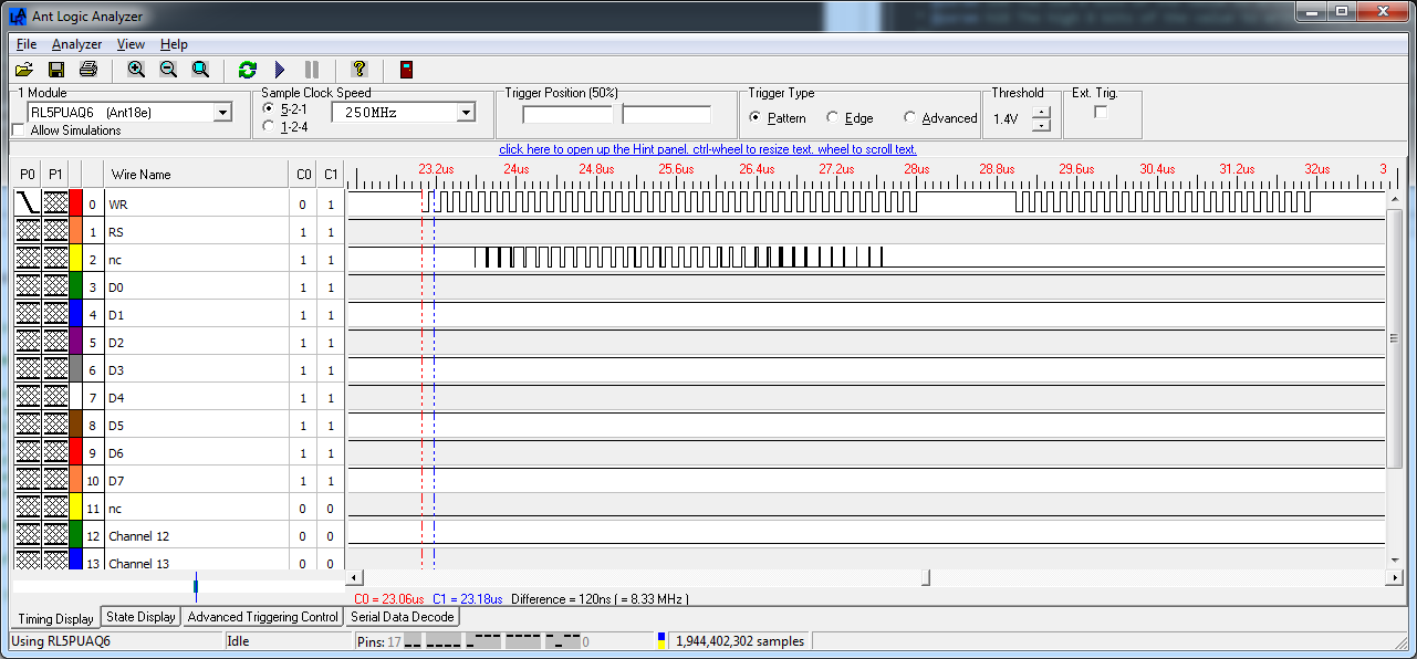

Click for larger
The first capture shows the effect of the optimised /WR toggling. As expected we are achieving a fill rate of 8 megapixels/second.
The second capture shows how much overhead is added by the code that subtracts 40 from the total and jumps back to execute the next block of 40 pixels. It is 1 microsecond.
So is it worth this hand-optimisation? Yes it definitely is. In the following sections where I show the panel drivers that I’ve written, the accompanying videos are all running this driver. You can see how fast the screen clearing, rectangle drawing, gradient drawing and solid ellipse drawing operations are for yourself.
Optimising the line drawing algorithm
The first versions of my driver code featured the Extremely Fast Line Drawing Algorithm. It seemed to perform well and so I didn’t turn my attention to optimising it.
Recently however, I was tipped off that the EFLA was suboptimal on an MCU without an intrinsic divide instruction and that the classic Bresenham would probably be be better. Time for some profiling. I implemented the Bresenham algorithm using the pseudo-code in the Wikipedia article under the Simplification header.
My pseudo-random line drawing example code runs over a fixed 5 second period. These are the timings that I got on an ILI9325 panel in 64K colours and portrait mode:
| Algorithm | Lines drawn in 5 seconds |
|---|---|
| EFLA | 1055 |
| Bresenham | 1110 |
Sure enough Bresenham is slightly faster. Not much, but enough to get me thinking about whether it could be further optimised for this library. In producing an optimised implementation we rely on some basic facts:
- All the pixels in the line are the same colour.
- The panels provide ‘windowed’ output with auto-increment in the X-direction.
- The panels allow X and Y positions to be changed independently.
Here’s the resulting code:
template<class TDevice,class TAccessMode>
inline void GraphicsLibrary<TDevice,TAccessMode>::drawLine(const Point& p1,const Point& p2) const {

  // optimisation for straight lines. filling rectangles is much more efficient than plotting points

  if(p1.X==p2.X)
    fillRectangle(Rectangle(p1.X,Min(p1.Y,p2.Y),1,Abs(p2.Y-p1.Y)+1));
  else if(p1.Y==p2.Y)
    fillRectangle(Rectangle(Min(p1.X,p2.X),p1.Y,Abs(p2.X-p1.X)+1,1));
  else {

    int16_t x0,x1,y0,y1;

    x0=p1.X;
    y0=p1.Y;
    x1=p2.X;
    y1=p2.Y;

    if(x0>x1) {

      // the optimiser does this swap method faster than
      // the xor-trick

      int16_t t;

      t=x0;
      x0=x1;
      x1=t;

      t=y0;
      y0=y1;
      y1=t;
    }

    // calculate constants up-front

    int16_t dx=x1-x0;
    int16_t dy=Abs(y1-y0);
    int16_t sy=y0<y1 ? 1 : -1;
    int16_t mdy=-dy;
    int16_t err=dx-dy;
    bool xinc;

    // set the drawing rectangle that we need and plot the first point

    this->moveTo(x0,y0,this->getXmax(),this->getYmax());
    this->beginWriting();
    this->writePixel(_foreground);

    while(x0!=x1 || y0!=y1) {

      int16_t e2=2*err;

      if(e2>mdy) {

        err-=dy;
        x0++;

        // make a note that X has incremented

        xinc=true;
      }
      else
        xinc=false;       // nothing happened to X

      if(x0==x1 && y0==y1) {

        if(xinc) {

          // plot the pending X increment before returning

          this->writePixelAgain(_foreground);
          break;
        }
      }

      if(e2<dx) {
        err+=dx;
        y0+=sy;

        // Y has changed. We're going to have to do a complete
        // pixel write after we've moved the bare minimum of
        // window pointers

        if(xinc)
          this->moveX(x0,this->getXmax());

        this->moveY(y0,this->getYmax());

        this->beginWriting();
        this->writePixel(_foreground);
      }
      else {

        // Y has not changed, if X has changed then all we need
        // to do is push out another pixel

        if(xinc)
          this->writePixelAgain(_foreground);
      }
    }
  }
}
The algorithm should be recognisable from the Wikipedia article. I initially set a window that extends from the first point to the far right and bottom of the panel. This means that in cases where two horizontal pixels have to be written out together I can omit the cursor movement entirely because the panel has done it automatically for me.
When I do have to move the cursor I am careful to only move it in the horizontal or vertical direction that’s required.
Running the line demo with this optimised implementation results in a score of 2060 lines, a solid 85% speed increase for very little effort. Here’s a chart showing the final scores:
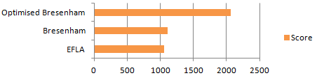
The actual speed increase obtained is variable and the flatter the line the better the increase. My demo draws pseudo-random lines so the speed increase that I quote could be viewed as an average.
Now that I have a solid pair of access modes I can move on to the driver templates that call upon their services to perform primitive operations.
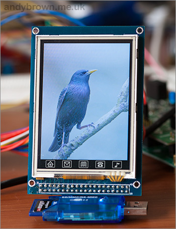
ILI9325
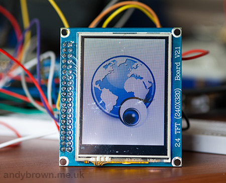
The ILI9325 is a very common QVGA controller found in many of the standalone panels that you see on the market as well as in panels that ship with MCU development boards. The ILI9325 panel that I have came packed with an STM32 development board, but there’s nothing to stop me detaching it and hooking it up to the Arduino as I’ve done here.
I’ve provided support for portrait and landscape orientations in the 64K (16-bit) colour mode. Hardware scrolling is supported in both orientations. To use the driver you need to include the header file.
#include "Generic16BitILI9325.h"
Typedefs are provided for all combinations of orientations and access modes. In all my examples I declare a panel using code similar to this:
typedef ILI9325_Landscape_64K_Gpio16Latch TftPanel;
//typedef ILI9325_Portrait_64K_Gpio16Latch TftPanel;
//typedef ILI9325_Landscape_64K_Xmem16 TftPanel;
//typedef ILI9325_Portrait_64K_Xmem16 TftPanel;
//TftPanel *tft=new TftPanel;
The commented out drivers are provided for reference. The first two are GPIO access modes and the last two are the XMEM modes.
My touch screen is looking a bit scuffed
Version 3.0.0 and above of the xmemtft library provides support for the ILI9325 and includes a suite of demos that you can use to get started. Here’s a video that shows the graphics library demo in action using the optimised GPIO driver.
ILI9327
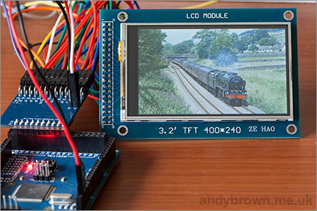
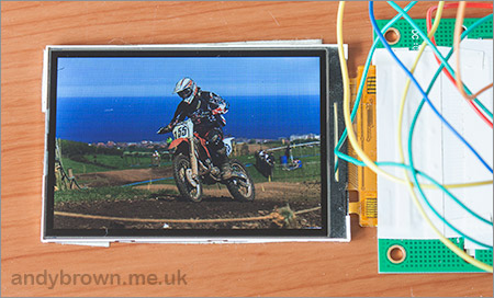
The ILI9327 controller provides a resolution of up to 432×240 pixels. This controller is not quite as common as the QVGA devices that you see everywhere.
The panel that I have is 400×240, 32 pixels fewer than the maximum available to the driver. The driver implements this by making the first 32 pixels invisible. That is, you can write to them but nothing will appear on the screen. I cater for this quirk with a ‘traits’ class provided as a parameter to the driver template.
I’ve provided support for portrait and landscape orientations in the 64K (16-bit) colour mode. Hardware scrolling is supported in both orientations. To use the driver you need to include the header file.
#include "Generic16BitILI9327.h"
Typedefs are provided for all combinations of orientations and access modes. In all my examples I declare a panel using code similar to this:
typedef ILI9327_400x240_Landscape_64K_Gpio16Latch TftPanel;
//typedef ILI9327_400x240_Portrait_64K_Gpio16Latch TftPanel;
//typedef ILI9327_400x240_Landscape_64K_Xmem16 TftPanel;
//typedef ILI9327_400x240_Portrait_64K_Xmem16 TftPanel;
//TftPanel *tft=new TftPanel;
The commented out drivers are provided for reference. The first two are GPIO access modes and the last two are the XMEM modes.
Version 3.0.0 and above of the xmemtft library provides support for the ILI9327 and includes a suite of demos that you can use to get started. Here’s a video that shows the graphics library demo in action using the optimised GPIO driver.
ILI9481
The ILI9481 controller from Ilitek is a 480×320 (HVGA) controller that is less commonly found in panels that you can get on ebay. There are four times as many pixels on an HVGA panel as there are on a QVGA panel so it was interesting to see how the graphics driver performs on this panel.
I’ve provided support for portrait and landscape orientations in the 64K (16-bit) colour mode. Hardware scrolling is supported in both orientations. To use the driver you need to include the header file.
#include "Generic16BitILI9481.h"
Typedefs are provided for all combinations of orientations and access modes. In all my examples I declare a panel using code similar to this:
typedef ILI9481_Landscape_64K_Gpio16Latch TftPanel;
//typedef ILI9481_Portrait_64K_Gpio16Latch TftPanel;
//typedef ILI9481_Landscape_64K_Xmem16 TftPanel;
//typedef ILI9481_Portrait_64K_Xmem16 TftPanel;
//TftPanel *tft=new TftPanel;
The commented out drivers are provided for reference. The first two are GPIO access modes and the last two are the XMEM modes.
Version 3.0.0 and above of the xmemtft library provides support for the ILI9481 and includes a suite of demos that you can use to get started. Here’s a video that shows the graphics library demo in action using the optimised GPIO driver. I was pleased to see that the operations that make most use of optimised fill algorithm, for example the gradient and clear screen demos, perform extremely quickly.
HX8347A
The HX8347A controller from Himax is a 320×240 (QVGA) device commonly featured in the LCD boards that you can get on ebay.
I’ve provided support for portrait and landscape orientations in the 64K (16-bit) colour mode. Hardware scrolling is supported in both orientations. To use the driver you need to include the header file.
#include "Generic16BitHX8347A.h"
Typedefs are provided for all combinations of orientations and access modes. In all my examples I declare a panel using code similar to this:
typedef HX8347A_Landscape_64K_Gpio16Latch TftPanel;
//typedef HX8347A_Portrait_64K_Gpio16Latch TftPanel;
//typedef HX8347A_Landscape_64K_Xmem16 TftPanel;
//typedef HX8347A_Portrait_64K_Xmem16 TftPanel;
//TftPanel *tft=new TftPanel;
The commented out drivers are provided for reference. The first two are GPIO access modes and the last two are the XMEM modes.
Version 3.0.0 and above of the xmemtft library provides support for the HX8347A and includes a suite of demos that you can use to get started. Here’s a video that shows the graphics library demo in action using the optimised GPIO driver.
Get the source code from github
As of version 3.0.0 you can now find all the source code on github.com. If you’re interested in extending the library or just curious as to how it works then please feel free to get involved.
If you don’t have or want a github account then you can download the pre-packaged release from my downloads page.
License change
This new release is now licensed under the terms of the Apache License, version 2. Previous versions used the BSD license and the reason for the change is primarily the migration of the source code to Github. The Apache license preserves all the rights that the BSD license conveyed, formally recognises and protects the role of the contributor and includes protection against patent abuse.
Build your own PCBs
I’ve released the gerber files for this project so that you can build your own PCBs. All you need to do is upload the zip file to one of the cheapo prototyping services that offer 10 copies of a 5x5cm board for about $10. Visit my downloads page to get the gerbers in zip file.