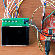


Interfacing the Nokia 6300 QVGA TFT to the standard Arduino
In two of my previous articles (here and here) I explained how we could connect the 8-bit 8080 interface presented by the TFT panel to the XMEM interface of the Arduino Mega to achieve a high performance full-colour graphical interface.
I went on to present a high-performance open-source template library for performing common graphical operations on the TFT panel. The result was a complete, ready-to-use graphical subsystem for users of the Arduino Mega.
In this follow-up article I will show you how to connect the same Nokia 6300 QVGA TFT panel to the standard Arduino Duemilanove or Uno. These limited devices present several challenges that we will need to overcome before we can put hand on heart and honestly say that we have a usable system.
The developer-in-a-hurry guide
Firstly, download at least version 2.0.0 of my library from my downloads page.
You can use nearly all my example code supplied with the library and presented in the previous article. All you need to do is append _Gpio to the name of the LCD driver and recompile:
//typedef Nokia6300_Landscape_262K LcdAccess;
typedef Nokia6300_Landscape_262K_Gpio LcdAccess;
Customising ports and pins
The default setup is for port D (which is pins 0..7) and pins 8 and 9 to be used for WR and RS respectively. If you want to change this then you need to edit GpioAccessMode.h which is located in the library installation directory. This is the section that you can customise:
				/*
				 * Here's where you choose the pins for the GPIO interface.
				 * Note that on the ATMega328P the data port has to be PORTD
				 */

				DATA_PORT = IO_PORTD,

				RS_PORT   = IO_PORTB,
				RS_PIN    = 1,
				WR_PORT   = IO_PORTB,
				WR_PIN    = 0
The port and pin definitions that you can select from are shown just above in the header file. The pin numbers (0..7) are indexes into the associated port. I have included comments that illustrate how the pin indexes map to Arduino pin numbers. For example:
IO_PORTB = 0x05, // 8,9,10,11,12,13,x,x
All the features are included, even the compressed LZG bitmaps. However, do recall that LZG bitmap support requires 2K of SRAM while working and that rules out its use on the Duemilanove and Uno devices.
Now, let’s continue with write-up that explains how we got here.
The ATMega328P
At the heart of the Arduino Uno (and Duemilanove, but I’m going to save myself some keystrokes by referring to both as the Uno from here on) is the ATMega328P MCU.
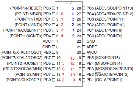
ATMega328P pinout. Arduino digital pins in red, analogue pins blue.
Not exactly brimming with GPIO pins is it? Worse still, they’re all heavily overloaded with on-chip peripherals so we’re really going to have to work to keep the pin usage down.
It runs at the same 16Mhz clock speed as the Mega1280 and Mega2560 but is significantly limited in terms of memory (32Kb flash/2Kb SRAM) and GPIO pins. We will need to overcome both of these limitations if we’re going to come with something that’s actually usable in your projects.
TFT to Arduino pin mapping
Here’s how we’re going to map the pins of the TFT to the pins on the Uno.
td>
| Function | Uno pin | ATMega Port | Port pin |
|---|---|---|---|
| D0 | 0 | D | 0 |
| D1 | 1 | D | 1 |
| D2 | 2 | D | 2 |
| D3 | 3 | D | 3 |
| D4 | 4 | D | 4 |
| D5 | 5 | D | 5 |
| D6 | 6 | D | 6 |
| D7 | 7 | D | 7 |
| WR | 8 | B | 0 |
| RS | 9 | B | 1 |
| CS | GND | n/a | n/a |
| VIO | 5V | n/a | n/a |
| VDD | 5V | n/a | n/a |
| RESET | RESET | n/a | n/a |
The use of pins 0-7 (PORTD) is fixed and cannot be changed. The reason for this is that we can only get usable performance by writing 8 bits to an entire port in one operation and PORTD (Uno pins 0..7) is the only port exposed in its entirety on the Uno.
The two power inputs, VDD and VIO, can be connected directly to the Ardunio’s 5V output. On my board VDD and VIO go through the level converter so they actually end up at the LCD as 3.3V which is what I consider to be the maximum safe level for the panel. On the Mega board I use GPIO pins for these power inputs so that I can control the order in which they come up. From experience I now know that this is not necessary and it’s safe to apply power in any order.
Our first optimisation saves us a GPIO pin. We chain the panel’s RESET input to the RESET output on the Uno, taking advantage of its compatible active-low operation.
The MC2PA8201 datasheet that we’re working from shows clearly that CS can be low (active) across multiple bus transactions and so we opt to save a pin and gain a little in performance by grounding it. A different design could use CS to multiplex the pins that we’ve taken for the LCD for other purposes whilst the LCD is not being written to.
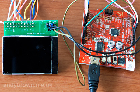
Connected to my Duemilanove clone
The two remaining control pins WR and RS could be moved to any other unused Uno pins. In this article we arbitrarily choose to use Arduino pins 8 and 9 which happen to be located on PORTB, pins 0 and 1.
Optimising the driver
I wrote a simple test program to help me to evaluate the results of my optimisations. It tests the raw pixel fill rate and measures a speed at which we can output text characters to the display. We’re using the 262K colour mode that requires three 8-bit transfers per pixel.
Here it is, all of it:
#include "Nokia6300.h"
#include "Font_volter_goldfish_9.h"
#include "ColourNames.h"

using namespace lcd;

/*
 * The orientation and colour depth that we will use
 */

typedef Nokia6300_Landscape_262K_Gpio LcdAccess;
LcdAccess *tft;
Font *font;

/*
 * Fill the screen and show pixels/sec
 */

void fillTest() {

	int32_t before,elapsed,persec;

	tft->setBackground(ColourNames::RED);

	before=millis();
	tft->clearScreen();
	elapsed=millis()-before;
	persec=76800000L/elapsed;

	tft->setBackground(ColourNames::BLACK);
	tft->setForeground(ColourNames::WHITE);

	*tft << Point(0,0)
			 << persec
			 << " pixels per second";

	delay(5000);
}


/*
 * Show random text and measure chars/sec
 */

void textTest() {

  int i;
  const char *str="The quick brown fox";
  Size size;
  Point p;
  LcdAccess::tCOLOUR randomColour;
  int32_t before,elapsed,persec;

  tft->setBackground(ColourNames::BLACK);
  tft->clearScreen();

  size=tft->measureString(*font,str);

  before=millis();
  for(i=0;i<500;i++) {

  	p.X=rand() % (tft->getXmax()-size.Width);
    p.Y=rand() % (tft->getYmax()-size.Height);

    randomColour=(((uint32_t)rand() << 16) | rand()) & 0xffffff;

    tft->setForeground(randomColour);
    *tft << p << str;
  }
  elapsed=millis()-before;
  persec=9500000L/elapsed;

  tft->setBackground(ColourNames::BLACK);
  tft->setForeground(ColourNames::WHITE);
  tft->clearScreen();

  *tft << Point(0,0)
  		 << persec
  		 << " characters per second";

  delay(5000);
}


void setup() {

	// create and initialise the panel and font

	tft=new LcdAccess;
	font=new Font_VOLTER__28GOLDFISH_299;

	// clear to black

	tft->setBackground(ColourNames::BLACK);
	tft->clearScreen();

	// select the font used througout

	*tft << *font;

	for(;;) {
		fillTest();
		textTest();
	}
}


void loop() {}
Basic implementation
Our basic implementation will focus on writing data and commands to the panel. I know this is going to perform poorly, but we need a straw man up and running so we can start the optimisation.
	inline void GpioAccessMode::writeData(uint8_t value) {

		digitalWrite(WR,LOW);
		digitalWrite(RS,HIGH);

		PORTD=value;

		digitalWrite(WR,HIGH);
	}
So there it is, the basic implementation of the 8080 protocol albeit with no respect for the timing requirements of the target panel because we don’t know for sure what they are! Let’s hope this works, your mileage may vary.
We initialise the control lines, write the data to the port and then pull WR high (data is transferred on the rising edge of WR). CS has been grounded so there’s no need to control it. A corresponding function for writing to a register exists but you don’t need to see that because the only difference is that RS is set LOW for the transaction.
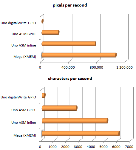
As expected, the performance is poor, spectacularly poor in fact. The fill rate and character output rate are just 1.0% and 3.2% respectively of the figures achieved by the XMEM interface. Let’s examine why by taking a look at the assembly language emitted by the compiler.
        inline void GpioAccessMode::writeData(uint8_t value) {
     616:       cf 93           push    r28
     618:       c8 2f           mov     r28, r24

                digitalWrite(WR,LOW);
     61a:       60 e0           ldi     r22, 0x00       ; 0
     61c:       88 e0           ldi     r24, 0x08       ; 8
     61e:       0e 94 ba 07     call    0xf74   ; 0xf74 <digitalWrite>
                digitalWrite(RS,HIGH);
     622:       61 e0           ldi     r22, 0x01       ; 1
     624:       89 e0           ldi     r24, 0x09       ; 9
     626:       0e 94 ba 07     call    0xf74   ; 0xf74 <digitalWrite>

                PORTD=value;
     62a:       cb b9           out     0x0b, r28       ; 11

                digitalWrite(WR,HIGH);
     62c:       61 e0           ldi     r22, 0x01       ; 1
     62e:       88 e0           ldi     r24, 0x08       ; 8
     630:       0e 94 ba 07     call    0xf74   ; 0xf74 <digitalWrite>
We can see that the compiler makes the expected calls to digitalWrite() and, on the highlighted line, uses the OUT instruction to write data to the port. This part is good. OUT is the fastest possible way to write all bits to a port.
So we can confirm what we suspected all along. digitalWrite() performs very poorly, but direct port access generates optimal assembly instructions. Our optimisations must not interfere with that.
First round of optimisations
Now, there are faster versions of the digitalWrite() function around on the internet and we could use that but it would not be optimal. Let’s go straight for the prize, get our hands dirty and write some embedded assembly language.
	inline void GpioAccessMode::writeData(uint8_t value) {

		// RS=high, WR = low
		asm volatile( "sbi %0, %1" :: "I" (RS_PORT), "I" (RS_PIN) );
		asm volatile( "cbi %0, %1" :: "I" (WR_PORT), "I" (WR_PIN) );

		// write the data
		asm volatile( "out %0, %1" :: "I" (DATA_PORT), "r" (value) );

		// WR = high
		asm volatile( "sbi %0, %1" :: "I" (WR_PORT), "I" (WR_PIN) );
	}
Here we’ve completely ditched the slow ‘C’ calls and hand-crafted the assembly language necessary to set and reset bits in the port registers. I have chosen to use individual sbi and cbi instructions so that the user has flexibility in choosing which ports and pins to use. Each one of these instructions costs 2 clock cycles.
I have also abstracted out the hardcoded port and pin numbers into enumerations in a header file so that they can be easily changed to suit the requirements of the project.
The results of this optimisation are dramatic. We are now up to 22.5% and 40.9% of the pixel fill-rate and character output rate of the XMEM interface, respectively.
Is this enough? No of course not, we can now widen the scope of our optimisation to include the calls to these core functions. Is there even more scope for optimisation?
The second round of optimisation
In this round we will make a further optimisation by noting that in use we generally do hundreds or even thousands of data writes for every one instruction write. Using this knowledge we will maintain the RS line in a HIGH state (date write) and only pull it low for an instruction write, after which we will put it back to HIGH. This allows us to ignore it completely for data writes (the common case).
	inline void GpioAccessMode::writeCommand(uint8_t cmd) {

		// RS,WR = low
		asm volatile( "cbi %0, %1" :: "I" (RS_PORT), "I" (RS_PIN) );
		asm volatile( "cbi %0, %1" :: "I" (WR_PORT), "I" (WR_PIN) );

		// write the command
		asm volatile( "out %0, %1" :: "I" (DATA_PORT), "r" (cmd) );

		// WR,RS = high
		asm volatile( "sbi %0, %1" :: "I" (WR_PORT), "I" (WR_PIN) );
		asm volatile( "sbi %0, %1" :: "I" (RS_PORT), "I" (RS_PIN) );
	}

	inline void GpioAccessMode::writeData(uint8_t value) {

		// WR = low
		asm volatile( "cbi %0, %1" :: "I" (WR_PORT), "I" (WR_PIN) );

		// write the data
		asm volatile( "out %0, %1" :: "I" (DATA_PORT), "r" (value) );

		// WR = high
		asm volatile( "sbi %0, %1" :: "I" (WR_PORT), "I" (WR_PIN) );
	}
The result of this is a useful uptick in speed. We are now up to 30.6% and 48.2% of the pixel and character fill rates of the XMEM interface, respectively.
Final optimisations
In this final round of optimisation we consider how the Arduino IDE will compile our code and tune accordingly. At the time of writing and for reasons I cannot fathom, the authors have decided that size optimisations (-Os) are all you’re ever going to want.
The impact of this arbitrary decision is that the compiler will refuse any optimisation that would increase the size of the output image. That means only the most basic of inlining will ever be considered. Aggressive inlining is out of the question and will never happen under a -Os compilation flag.
To work around this we will replace the writeData() and writeCommand() functions that are at the core of our driver with some rather fugly pre-processor macros.
#define GPIO_WRITE_REGISTER_ADDRESS(cmd) \
	asm volatile( "cbi %0, %1" :: "I" (RS_PORT), "I" (RS_PIN) ); \
	asm volatile( "cbi %0, %1" :: "I" (WR_PORT), "I" (WR_PIN) ); \
	asm volatile( "out %0, %1" :: "I" (DATA_PORT), "r" (cmd) );  \
	asm volatile( "sbi %0, %1" :: "I" (WR_PORT), "I" (WR_PIN) ); \
	asm volatile( "sbi %0, %1" :: "I" (RS_PORT), "I" (RS_PIN) );

#define GPIO_WRITE_DATA_ADDRESS(value)	\
	asm volatile( "cbi %0, %1" :: "I" (WR_PORT), "I" (WR_PIN) );  \
	asm volatile( "out %0, %1" :: "I" (DATA_PORT), "r" (value) ); \
	asm volatile( "sbi %0, %1" :: "I" (WR_PORT), "I" (WR_PIN) );

#define GPIO_WRITE_COMMAND(cmd,parameter)  \
	GPIO_WRITE_REGISTER_ADDRESS(cmd);  \
	GPIO_WRITE_DATA_ADDRESS(parameter);
The impact of this is nothing short of spectacular. The overall speed more than doubles and we are now running at 72.2% and 67.8% of the pixel and character fill rates of the XMEM interface, respectively. We would not have to do this if the IDE would allow us to choose -O2 or -O3: the compiler would do it for us.
Performance summary
Final thoughts
If you want to really squeeze the last drop of performance from the driver then there is further scope for some assembly optimisation if you are prepared to accept the (slight) limitation that the WR and RS pins must be on the same IO port.
In the writeCommand() function we begin and end the sequence with a pair of cbi and sbi instructions, like this:
asm volatile( "cbi %0, %1" :: "I" (RS_PORT), "I" (RS_PIN) );
asm volatile( "cbi %0, %1" :: "I" (WR_PORT), "I" (WR_PIN) );
These instructions cost us two clock cycles each, giving an overhead of eight cycles for each call to the writeCommand() function.
If we assume that RS and WR are on the same port then it is faster to read the port state with the in instruction, set or reset both bits simultaneously with an or or an and instruction and then write back the port state with an out instruction.
Each of those instructions costs just one CPU cycle meaning that we could reduce the overall cost to six cycles, down from eight in the generic implementation.
I don’t want to impose the single-port limit on everyone so I’ve left my implementation as-is. This final optimisation suggestion is left as an exercise for the reader.
Watch the video
I’ve hacked together a short video that visually illustrates the difference in performance between the XMEM implementation on the Mega and the optimised inline ASM GPIO implementation on my Seeeduino (Duemilanove clone) board. I think you’ll agree that the GPIO performance is very good.