


LCD backlight and contrast manager
This article will present a circuit and accompanying source code that you can use to control the backlight and contrast functions of an HD44780-compatible LCD.
Controlling these functions from software allows you to cut down on external components such as dials, saving you space and money.
Goals of the project
The goals of this project are as follows
- Control backlight and contrast via Arduino PWM pins.
- Allow direct setting of values and fade-in/fade-out modes.
- Provide power-saving functionality to switch off the backlight until woken up.
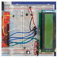
Circuit diagram
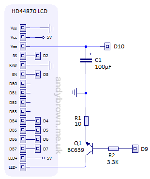
The circuit diagram shows the 16 pins of the HD44780 controller on the left together with our control circuitry on the right. Arduino pins are labelled Dn. You are free to use any Arduino pins that you like for the main LCD but you must use PWM pins for the ones labelled D9/D10 in the diagram.
The brightness of the LCD backlight will be controlled by a transistor used to regulate the current that flows through the internal LEDs. The contrast will be controlled by a filtered PWM signal generated by the Arduino.
Choosing the LCD
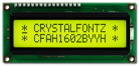
You can use any character LCD having a controller that is compatible with the HD44780. The cheapest source of these devices is usually direct from China from an ebay seller but try to get hold of the datasheet before you buy because nothing is likely to come with it. You can also buy them from online electronics stores or direct from a supplier such as CrystalFontz. The CrystalFontz devices come with a very comprehensive and well-written datasheet.
For this article I will use a 16×2 CrystalFontz CFAH1602B display.
Choosing R1
The resistor R1 should be chosen so that when the transistor is fully open the current that flows is just enough to light the backlight at full brightness. The datasheet for the LCD gives the maximum backlight current as 130mA. This value is low enough that we can connect LED+ to the 5V pin on the Arduino. If it were much higher then we would have to drive LED+ via a separate 7805 regulator to avoid overloading the Arduino
The datasheet applies Ohm’s law using the following equation to calculate an ideal value for R1.
6 ohms is not a popular size of resistor and I don’t have one to hand, nor do I have an easy combination that I could use in parallel, so I will default to the next one up that I have, 10 ohms. This will yield a current of 80mA.
Choosing Q1
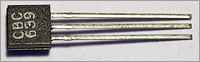
Almost any general purpose NPN transistor will work here. You just need to check that it can handle the maximum current that you are going to supply to the backlight. In the transistor datasheet this will be referred to as the collector current, or Ic. I had a BC639 in my random bits box and it can handle 1000mA at the collector, more than enough for my needs.
Choosing R2
The resistor R2 is used to regulate the current to the base of the transistor. We need to choose a value for R1 that will allow the transistor to pass the desired 80mA when the maximum 5V average voltage comes from the Arduino PWM pin. The transistor equation is:
![]()
Iec=80mA and I measured the gain (beta) of the transistor using a multimeter to be 65. So, solving the equation we have Ieb = 1.23mA. Applying ohm’s law we get a value for R2 when the supply voltage is 5V of 4062 ohms. This is not a common value for a resistor and the nearest that I have is 3K3. This will result in 1.25mA. Close enough.
Choosing C1
The LCD ‘contrast’ pin Vee is used to control the LCD driving voltage. You can supply anywhere between 0V and Vcc (5V) and the LCD will then drive the display using a voltage of Vcc – Vee.
The problem is that the square wave PWM output from the Arduino at the default frequency of about 500Hz is not fast enough to fool the LCD into producing a continuous display. If you hook up the PWM pin directly to Vee then you will most likely see a shimmering effect as the LCD rapidly changes driving voltage.
The solution is to filter the PWM output using a low-pass capacitor so that the output wave looks more flat. It won’t be perfect, but it should be enough to get a steady display on the LCD throughout the acceptable contrast range. The value for the capacitor should be fairly large. Start with 100uF and if that’s not enough then try 220uF or 470uF.
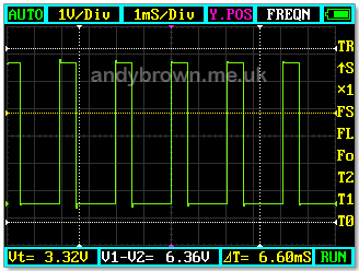
This is what a PWM waveform looks like without any filtering.
After filtering with the 100uF capacitor shown in the circuit diagram the wave looks like this:
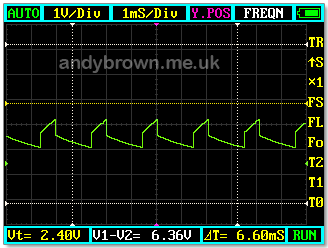
It’s far from a perfectly smooth wave but the deviations from the average are small enough that the LCD will appear to be perfectly steady.
The software interface
Here’s the header file that defines the interface to the adjustments manager.
/*
 * LCD Adjustments: Copyright (c) 2010 Andy Brown
 * http://www.andybrown.me.uk
 *
 * This work is licensed under a Creative Commons
 * Attribution_ShareAlike 3.0 Unported License.
 * http://creativecommons.org/licenses/by_sa/3.0/
 */

#ifndef __B66E1DAA_232C_4362_86C4_86F942C1F9C8
#define __B66E1DAA_232C_4362_86C4_86F942C1F9C8

#include <stdint.h>

/*
 * LCD Adjustments header file
 */

class LCDAdjustments
{
public:
	class PWMManager
	{
	private:
		uint8_t _pin;
		uint8_t _currentValue;
		uint8_t _defaultPercentage;

	public:
		// initialize on a PWM pin
		void setup(uint8_t pin_,uint8_t defaultValue_);

		// reset to the default percentage
		void reset();

		// set percent value immediately
		void setPercentage(uint8_t percentage_);

		// set absolute value immediately
		void setValue(uint8_t value_);

		// fade to the target percentage
		void fadeToPercentage(
				uint8_t targetPercentage_,
				uint32_t microsPerStep_);

		// fade to the target value
		void fadeToValue(
				uint8_t targetValue_,
				uint32_t microsPerStep_);

		// convert a percentage to an absolute value
		uint8_t percentageToValue(uint8_t value_) const;

		// get the current value
		uint8_t getCurrentValue() const;
	};

private:
	// brightness manager
	PWMManager _brightness;

	// contrast manager
	PWMManager _contrast;

	// saved power saving value
	uint8_t _powerSavingValue;

public:
	// create the class
	void setup(
			uint8_t brightnessPin_,
			uint8_t contrastPin_,
			uint8_t initialBrightnessPercent_,
			uint8_t initialContrastPercent_);

	// get the brightness handler
	PWMManager& brightness();

	// get the contrast handler
	PWMManager& contrast();

	// enter power saving immediately
	void enterPowerSaving();

	// enter power saving by fade out
	void enterPowerSaving(uint32_t microsPerStep_);

	// exit power saving immediately
	void exitPowerSaving();

	// exit power saving, fading up
	void exitPowerSaving(uint32_t microsPerStep_);
};

#endif
LCDAdjustments.h
Initialising the class
To initialise the class before you use it, you must call setup().
void setup(
  uint8_t brightnessPin_,
  uint8_t contrastPin_,
  uint8_t initialBrightnessPercent_,
  uint8_t initialContrastPercent_
);
The brightness and contrast pins must be capable of doing hardware PWM. The initial values will be loaded immediately and can be reverted back to by calling reset(). Percentage values are integers between 0 and 100 inclusive. For example, to use pins 9 and 10 with default values of 100 (brightness) and 30 (contrast):
LCDAdjustments adjustments;
adjustments.setup(9,10,100,30);
Setting a new value
setValue() and setPercentage() will set values with a range of 0-255 (setValue) or 0-100 (setPercentage). For example, to set the brightness to 50% and the contrast to 30%:
adjustments.brightness().setPercentage(50);
adjustments.contrast().setPercentage(30);
A note about the contrast
You will need to determine the acceptable contrast values empirically. The CrystalFontz LCD used in this article can only sensibly handle a range of 10% to 40%. Below 10% the LCD display appears as solid blocks and above 40% the text disappears completely. Go too far above 40% and the display will malfunction showing random characters. You will need to perform your own experiments and then set suitable limits in your code.
Fading to a new value
fadeToValue() and fadeToPercentage() will smoothly fade the current LCD value up or down to the desired target in a visually pleasing manner.
		// fade to the target percentage
		void fadeToPercentage(
				uint8_t targetPercentage_,
				uint32_t microsPerStep_);

		// fade to the target value
		void fadeToValue(
				uint8_t targetValue_,
				uint32_t microsPerStep_);
microsPerStep_ is the number of microseconds to wait between each transition in the animation sequence. I have found that between 2000 and 3000 are good choices. These methods are synchronous, that is they will block for the total time it takes to do the fade. For example, to fade the brightness to zero with 2500μs between each step:
adjustments.brightness().fadeToPercentage(0,2500);
Power saving
The class provides a ‘power saving’ function. That is, it can switch off the LCD backlight and then restore it to its previous value when woken up. The methods used to enter power-saving are:
	// enter power saving immediately
	void enterPowerSaving();

	// enter power saving by fade out
	void enterPowerSaving(uint32_t microsPerStep_);
enterPowerSaving() will switch off the backlight immediately. enterPowerSaving(uint32_t microsPerStep_) will switch off the backlight by fading it out to zero in a visually pleasing manner. For example, to enter power saving by fading out:
adjustments.enterPowerSaving(2500);
When you want to exit from power saving you have the following methods to do it:
	// exit power saving immediately
	void exitPowerSaving();

	// exit power saving, fading up
	void exitPowerSaving(uint32_t microsPerStep_);
These methods will restore the previous value of the LCD brightness either immediately or via a fade-in effect. For example, to immediately restore the brightness:
adjustments.exitPowerSaving();
Source Code
Here’s LCDAdjustments.cpp that contains the implementation.
/*
 * LCD Adjustments: Copyright (c) 2010 Andy Brown
 * http://www.andybrown.me.uk
 *
 * This work is licensed under a Creative Commons
 * Attribution-ShareAlike 3.0 Unported License.
 * http://creativecommons.org/licenses/by-sa/3.0/
 */

#include "LCDAdjustments.h"
#include <wiring.h>


/*
 * Setup the class with pins
 */

void LCDAdjustments::setup(
		uint8_t brightnessPin_,
		uint8_t contrastPin_,
		uint8_t initialBrightness_,
		uint8_t initialContrast_)
{
  // 32Khz on 9/10
	//TCCR1B=1;

	// setup the brightness
	_brightness.setup(brightnessPin_,initialBrightness_);

	// setup the contrast
	_contrast.setup(contrastPin_,initialContrast_);
}


/*
 * Return the brightness manager
 */

LCDAdjustments::PWMManager &LCDAdjustments::brightness()
{
	return _brightness;
}


/*
 * Return the contrast manager
 */

LCDAdjustments::PWMManager& LCDAdjustments::contrast()
{
	return _contrast;
}


/*
 * Enter power saving immediately
 */

void LCDAdjustments::enterPowerSaving()
{
// save the current value and switch off the backlight

	_powerSavingValue=_brightness.getCurrentValue();
	_brightness.setValue(0);
}


/*
 * Enter power saving with fade
 */

void LCDAdjustments::enterPowerSaving(uint32_t microsPerStep_)
{
// save current value and fade out the backlight

	_powerSavingValue=_brightness.getCurrentValue();
	_brightness.fadeToPercentage(0,microsPerStep_);
}


/*
 * Exit from power saving immediately
 */

void LCDAdjustments::exitPowerSaving()
{
	_brightness.setValue(_powerSavingValue);
}


/*
 * Exit from power saving with fade up
 */

void LCDAdjustments::exitPowerSaving(uint32_t microsPerStep_)
{
	_brightness.fadeToValue(_powerSavingValue,microsPerStep_);
}


/*
 * Setup the PWM manager
 */

void LCDAdjustments::PWMManager::setup(
		uint8_t pin_,
		uint8_t defaultPercentage_)
{
	_pin=pin_;
	_defaultPercentage=defaultPercentage_;

	pinMode(pin_,OUTPUT);
	setPercentage(defaultPercentage_);
}


/*
 * Set the value immediately
 */

void LCDAdjustments::PWMManager::setPercentage(uint8_t percentage_)
{
	setValue(percentageToValue(percentage_));
}


/*
 * Set the absolute value
 */

void LCDAdjustments::PWMManager::setValue(uint8_t value_)
{
// save the current value and write it to the pin

	_currentValue=value_;
	analogWrite(_pin,value_);
}


/**
 * Fade to a given percentage
 */

void LCDAdjustments::PWMManager::fadeToPercentage(
		uint8_t targetPercentage_,
		uint32_t microsPerStep_)
{
	fadeToValue(percentageToValue(targetPercentage_),microsPerStep_);
}


/**
 * Fade to a given value
 */

void LCDAdjustments::PWMManager::fadeToValue(
		uint8_t targetValue_,
		uint32_t microsPerStep_)
{
	int8_t direction;

	// figure out whether we're going up or down
	direction=targetValue_>_currentValue ? 1 : -1;

	while(_currentValue!=targetValue_)
	{
		setValue(_currentValue+direction);
		delayMicroseconds(microsPerStep_);
	}
}


/*
 * Convert percentage to absolute value
 */

uint8_t LCDAdjustments::PWMManager::percentageToValue(uint8_t percentage_) const
{
	return static_cast<uint8_t>((255*(int)percentage_)/100);
}


/*
 * Reset to the default percentage
 */

void LCDAdjustments::PWMManager::reset()
{
	setPercentage(_defaultPercentage);
}


/*
 * Get the current value
 */

uint8_t LCDAdjustments::PWMManager::getCurrentValue() const
{
	return _currentValue;
}
LCDAdjustments.cpp
Test Project
I built an Eclipse test project to exercise all the functionality of this class. You can download it from my downloads page.
click to enlarge
The test project has a dependency on the Arduino libraries for Eclipse that you can also get from my downloads page. You may have to adjust the Eclipse compiler C++ include and link settings to reflect the location of the Arduino libraries on your PC.
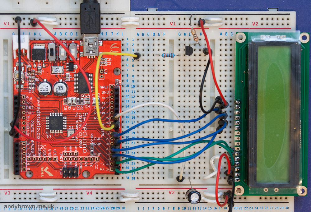
Here’s a video that shows the 16×2 LCD connected up to my Seeeduino board and running the test class.