Generic Nokia LCD hacking board
Over the course of the last few months I’ve been presenting schematics and PCBs that you can use to attach various Nokia LCDs to popular microcontrollers. Today I’m going to go one step further and present the generic board that I use for hacking any Nokia LCD that happens to have one of the correct connectors.
The schematic
The aim of this project is to do the following:
- Break out the 24R-JANK-GSAN-TF connector used by all the QVGA LCDs that I’ve reverse engineered on this site such as the Nokia 2730, 6300, N82, N95 8Gb and N93.
- Break out the Hirose DF23-10 connector used by the Nokia 6100 and 1600.
- Break out the Hirose DF23-22 connector used by the Nokia 6101 and others.
- Provide an optional OnSemi NCP5007 LED driver for the backlights that are powered by up to 4 LEDs in series.
With those goals in mind, let’s take a look at the schematic. This image is really small. Click on it to download the schematic as a PDF.
SV1 is the 0.1″ breakout header. It has up to 24 pins mapped to the Nokia connectors, V+ and V- that correspond to the output and feedback pins for the backlight driver, EN for the backlight driver enable pin, and several VCC and GND pins.
SV2 is the 24R-JANK-GSAN-TF connector. All 24 pins are mapped to the breakout header.
SV3 is the Hirose DF23-10 connector. This connector only has 10 pins and so they are mapped to pins P1..10 on the breakout connector.
SV4 is the Hirose DF23-22 connector. This connector has 22 pins that get mapped to pins P1..22 on the breakout connector.
Here’s the complete bill of materials for this schematic.
| Part | Value | Device | Package |
|---|---|---|---|
| SV1 | pin header | MA15-2 | MA15-2 |
| SV2 | Nokia 12×2 | 24R-JANK-GSAN-TF | 12×2 |
| SV3 | Nokia 5×2 | Hirose DF23-10 | 5×2 |
| SV4 | Nokia 11×2 | Hirose DF23-22 | 11×2 |
| C1 | 4.7µF | ceramic | 0805 |
| C2 | 1µF 50V | ceramic | 0805 |
| D1 | CD214A-B140LF | Bourns schottky diode | DO214AC |
| L1 | 22µH | Murata LQH3NP_J0 inductor | 1212 |
| R1 | 10Ω 1% | resistor | 0805 |
| U1 | NCP5007 | OnSemi LED driver | SOT23-5 |
The NCP5007 backlight driver is a boost converter that works by continuously raising its output voltage until it overcomes the forward voltage of the LEDs and current starts to flow. It then continues to raise the voltage until the configured current level is detected (I set this to 20mA with a 10Ω resistor in all my designs).
An important side effect of this design is that the V+ and V- pins must not be left as an open circuit when the device is powered because it will cause the NCP5007 to endlessly raise its voltage output until it either burns out or automatically shuts down. OnSemi, the manufacturer, claims that it has an automatic shutdown for this case but you really don’t want to test that claim.
The PCB layout
With the schematic design now finalised, I set about designing the PCB.

Click for a PDF
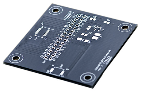
There wasn’t enough space within the target of 50x50mm to fit all the connectors on the top side so I placed the backlight, breakout, 24R-JANK-GSAN-TF and DF23-10 connectors on the top and the DF23-22 on the bottom.
Having a connector on the bottom meant that I would need to provide mounting holes for some feet to lift it off my workspace and so there are four 3mm holes provided in the corners.
Time for manufacturing!
I use the PCB manufacturing service provided by ITead Studio. After uploading the board to their site it takes between two and three weeks for the finished items to arrive in the mail.
In a nod to the illicit, underground nature of a reverse engineering board I decided to get them printed with a black solder mask. I know, I need to get out more often.

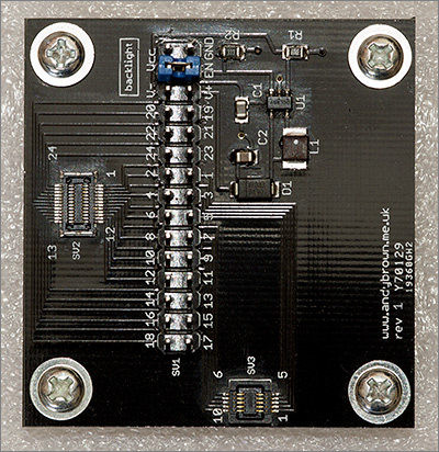
They look great in black but are nigh on impossible to photograph. I had to hold it at just the right angle to the light to make the features stand out.
Here’s an image that shows the front of the PCB with the backlight circuit, 24R-JANK-GSAN-TF and the DF23-10 connectors affixed.

Pin mappings for popular TFTs
During the time I spent reverse engineering the various displays I kept notes about the pin mappings. In this section I’ll present those mappings for some of the popular Nokia LCDs.
In the tables below, ‘board pin’ is the P0..Pn label on my board and ‘schematic pin’ is the pin number on the Nokia schematic found in the repair manual for the corresponding phone.
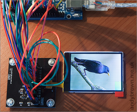
Note that these mappings are correct for an LCD connected in the orientation shown in the photograph below.
6300
| Also known as | Connector |
|---|---|
| 6300, 6301, 5310, 7500, 8600, 6120C, E90 (small), E51 | SV2 |
| Board pin | Function | schematic pin | Notes |
|---|---|---|---|
| 1 | LED1- | 1 | connect to LED2+ |
| 2 | LED2- | 2 | connect to V- |
| 3 | VDDI | 3 | connect to 3.3V |
| 4 | GND | 4 | |
| 5 | WR | 5 | |
| 6 | D0 | 6 | |
| 7 | GND | 7 | |
| 8 | D2 | 8 | |
| 9 | D4 | 9 | |
| 10 | D6 | 10 | |
| 11 | CS | 11 | |
| 12 | RESET | 12 | |
| 13 | TE | 13 | |
| 14 | D7 | 14 | |
| 15 | D5 | 15 | |
| 16 | GND | 16 | |
| 17 | D3 | 17 | |
| 18 | D1 | 18 | |
| 19 | RS | 19 | |
| 20 | RD | 20 | |
| 21 | GND | 21 | |
| 22 | VDD | 22 | connect to 3.3V |
| 23 | LED2+ | 23 | connect to LED1- |
| 24 | LED1+ | 24 | connect to V+ |
I used the pinout in the above table to connect the board to a Nokia 6300 LCD obtained from ebay. I connected them to an STM32F103VET6 board and ran the mcp2pa8201 demo supplied with my stm32plus library.

The above image shows the LCD driven by the STM32 via the hacking board.
N82
| Also known as | Connector |
|---|---|
| N79 N78 N77 E66 6210 | SV2 |
| Board pin | Function | schematic pin | Notes |
|---|---|---|---|
| 1 | LED- | 1 | connect to V- |
| 2 | GND | 2 | |
| 3 | VDDI | 3 | connect to 3.3V |
| 4 | GND | 4 | |
| 5 | WR | 5 | |
| 6 | D0 | 6 | |
| 7 | GND | 7 | |
| 8 | D2 | 8 | |
| 9 | D4 | 9 | |
| 10 | D6 | 10 | |
| 11 | CS | 11 | |
| 12 | RESET | 12 | |
| 13 | TE | 13 | |
| 14 | D7 | 14 | |
| 15 | D5 | 15 | |
| 16 | GND | 16 | |
| 17 | D3 | 17 | |
| 18 | D1 | 18 | |
| 19 | RS | 19 | |
| 20 | RD | 20 | |
| 21 | GND | 21 | |
| 22 | VDD | 22 | connect to 3.3V |
| 23 | GND | 23 | |
| 24 | LED+ | 24 | connect to V+ |
N95 8GB
| Also known as | Connector |
|---|---|
| n/a | SV2 |
| Board pin | Function | schematic pin | Notes |
|---|---|---|---|
| 1 | VDD | 13 | connect to 3.3V |
| 2 | GND | 14 | |
| 3 | TE | 15 | |
| 4 | RESET | 16 | |
| 5 | D1 | 17 | |
| 6 | D3 | 18 | |
| 7 | D5 | 19 | |
| 8 | D7 | 20 | |
| 9 | RS | 21 | |
| 10 | RD | 22 | |
| 11 | GND | 23 | |
| 12 | VIO | 24 | connect to 3.3V |
| 13 | GND | 1 | labelled KBBC on schematic |
| 14 | GND | 2 | |
| 15 | WR | 3 | |
| 16 | CS | 4 | |
| 17 | D6 | 5 | |
| 18 | D4 | 6 | |
| 19 | D2 | 7 | |
| 20 | D0 | 8 | |
| 21 | GND | 9 | |
| 22 | VIO | 10 | connect to 3.3V |
| 23 | GND | 11 | |
| 24 | VDD | 12 | connect to 3.3V |
Schematics, CAD and gerbers available
I have open-sourced my PCB design and CAD files so if you’re interested in building your own boards then head on over to my downloads page and grab yourself a copy.


