


A review of the Maximator Altera FPGA development board
I recently received a review sample of a rather nice looking FPGA development board called Maximator from the folks at Kamami.com. I’ve spent some time evaluating it and this post is a detailed review of the board.
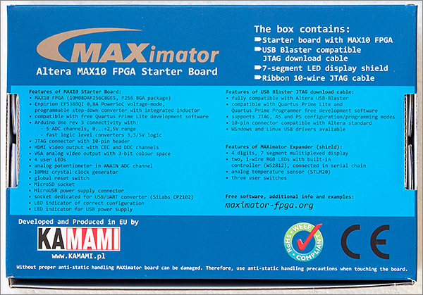
The development kit arrives in a nice, well padded box.
What’s in the box
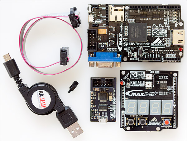
Inside the box you get the following parts.
- The Maximator FPGA board
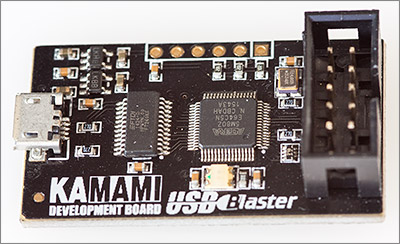
- A USB blaster programming board and 10-pin 2.54mm IDC cable.
- A micro USB cable
- An expansion shield containing four 7-segment LEDs, 2 PLCC RGB leds, 2 buttons, a reset button and a temperature sensor.
- An adjustment screw for the onboard potentiometer
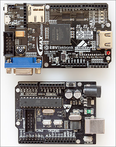
The Maximator board
The board itself is laid out in the Arduino format with the same number of GPIO pins arranged in that same, familiar format. The mounting screws are in the same place so it can be screwed into cases designed for the Arduino although physically it’s about 20mm longer than the Arduino.
Pride of place on the Maximator is given to the Altera MAX10 FPGA, part number 10M08DAF256C8GES. This is a decent size FPGA with 8000 logic elements, 500 CLBs, 387072 bits of RAM and 178 IOs.
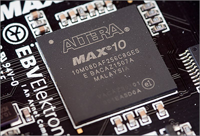
For a board aimed at beginners, that’s quite a lot of resources to play with. Unfortunately there are no user GPIOs beyond the limited set offered by the Arduino pins. The designers have used Altium Designer to create the board and you can download the schematic and PCB designer print from their website. You can see from the PCB print that the the board is a two layer design which would limit the number of IOs that can be routed out of the 256-ball BGA package and the designers have chosen to devote the non-GPIO pins to the onboard peripherals, of which there are a good number to choose from.
The onboard peripherals
The basic Arduino is a 5V board throughout and the designers of the Maximator would like you to be able to use Arduino shields with their design. That presents a power supply problem. FPGAs are a little more fussy about their power supply than the Arduino. The general pattern is that there’ll be at least two supplies, sometimes three. There’ll be a low voltage supply for the FPGA core and on the Maximator that’s 1.2V. FPGAs have something of a reputation for power consumption and reducing the core voltage has been one of the ways the manufacturers have tackled the issue.
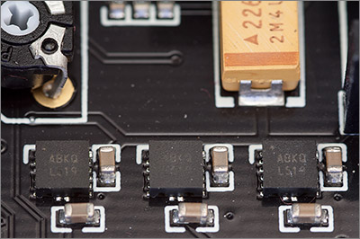
The 3 tiny QFN power supplies
There’ll be another power supply that drives the IO buffers and sometimes another one for the programming circuits. The IOs on this board run at 3.3V and there’s a third 2.5V supply that’s being used as the reference voltage for the 12-bit, 1Msps onboard ADC.
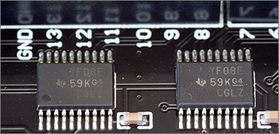
The 5V issue is tackled with a bank of level converters that ensure the ‘digital pins’ are driven at 5V. These are bi-direction level converters with a maximum speed of 110Mbit/s, definitely more than enough for the 2.54mm header connectors that they’re hooked up to.
The analog pins are limited to the 0-2.5V range by clamping diodes. You could probably get away with using these pins as GPIO but you’d be dumping current driven by any voltage above 2.5V on to the output pin of the 2.5V regulator which is not a good strategy for long term reliability.
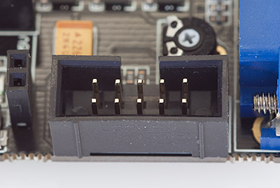
There’s a JTAG connector with its familiar 10-pin IDC box connector. This is where you connect up your USB blaster for programming the device.
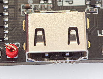
A full size HDMI connector provides digital video connectivity. You’ll need to write your own design to drive the HDMI connector or get hold of an existing IP core from somewhere.
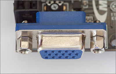
The VGA connector provides analogue video output and there’s a demo design on the Maximator website that shows off this capability.
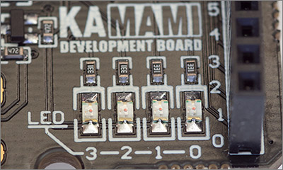
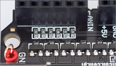
There are of course a selection of LEDs, four of them on this board.
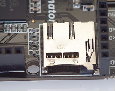
A micro-SD card provides access to external storage. Only the DATA0 pin is wired up so you’re limited to the simple 1-bit protocol. Full 4-bit SDIO access is not possible and would be very complex to implement anyway.
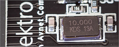
A 10MHz clock generator is provided that’s linked to one of the FPGA dedicated clock input pins. A quick look at the MAX10 datasheet reveals that these inputs can be linked to the onboard PLLs that appear to have programmable mulipliers and dividers that should allow you to generate whatever frequency you need your design to run at.
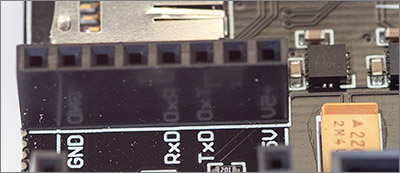
This connector is designed to accept a Silabs CP2102 USB/UART connector.
The expansion shield

The expansion shield adds four 7-segment LEDs, 2 PLCC RGB LEDs and two additional pushbuttons labelled L and R to the board. The examples on the Maximator website include demo designs for the expansion shield.
Using the board
I’ll admit it, I’m a Xilinx guy and I’m familiar with the (now deprecated) Xilinx ISE development suite so the Altera environment is going to be all new to me.
The first thing you need to do is download the free Altera Quartus Prime Lite development package and make sure that you select the option to include support for the MAX10 series. You need to register to download it but you can enter fake contact details and a throwaway email address to dodge the inevitable spam that follows on from forms like these. Just like Xilinx ISE, the download package somehow manages to be more than a gigabyte so set aside sufficient time for it to complete.
Installation on Windows 10 is straightforward but it should be noted that I accepted the default c:\altera_lite installation location. If you’re working on a locked down workstation then there’s no chance you’ll be able to write to the root of the system drive so you’d need to find someone who has admin rights to install it for you.
Double-clicking the desktop icon brings up the IDE user interface.
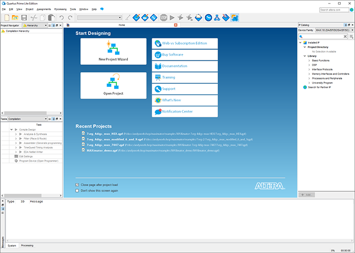
The UI only appears to be about 10 years behind modern standards which counts as recent in the FPGA software world. I found it perfectly useable, intuitive and more importantly, stable. The first thing I wanted to do was try out one of the examples provided by Maximator on their website so I downloaded the first of the 7-segment examples titled Project based on 7447.
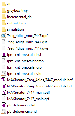
The zip file contains the Quartus .qpf project file that can be opened in the IDE as well as what looks like a simulation project. Opening the project transforms the IDE into a form that should be instantly recognizable to a Xilinx ISE user. Over on the left there’s a panel that shows the tasks involved in taking your design from source code to the binary format required by the FPGA.
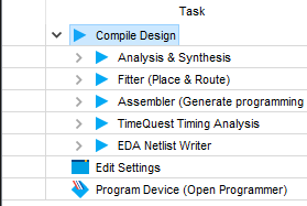
To build your design you just need to double-click on the Compile Design task. The build completed without a hitch so now I need to figure out how to upload the design to the board. I plugged in the USB blaster and it wanted drivers to be installed. The drivers can be found in the C:\altera_lite\15.1\quartus\drivers directory.
I quickly found the programming option under the Tools -> Programmer menu option. Clicking on the Hardware Setup button allowed me to select the USB Blaster option. Clicking on the Auto-Detect button successfully detected the MAX10 series and I selected the 10M08DA from the list of possible devices.
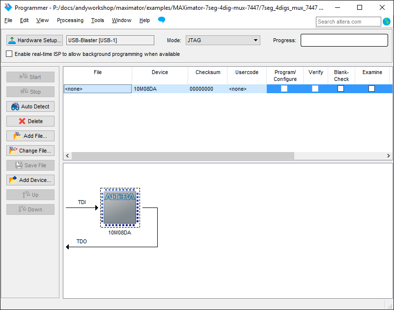
It still says none under the file column so I need to click Add File… to select the compiled design. The output is locatd in the output_files directory and there’s a choice of either a .pof or a .sof file. Googling around revealed these to be a programmer object file and a SRAM object file but gave no hint about which one I needed to use for this project. The answer came in the YouTube video that accompanies the example on the Maximator site. I could see that they were using the .sof file.
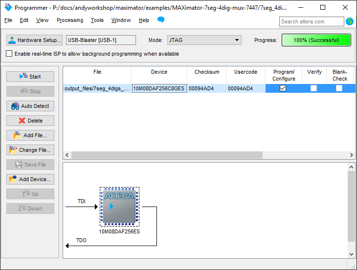
Make sure that you remove the ‘none’ entry from the list before clicking ‘Start’. For me this just worked, programming was successful and I could use the L and R buttons on the board to increase and decrease the number on the display.
The great thing about this MAX10 FPGA is that your designs are stored in non-volatile memory on-board which means that there is no need to program it when it’s powered up, reducing the external parts count and making the device effectively instant-on.
Power consumption
Power consumption is design-dependent. Altera and Xilinx both supply tools that can be used to estimate power consumption based on data gathered from a simulation run. With the Maximator we can just run it and see how much current is being drawn.
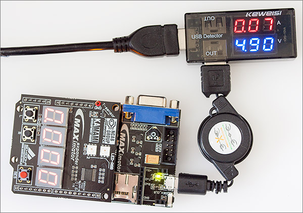
This particular design is drawing about 70mA and that includes the 7-segment LEDs.
Videos
I’ve put together a couple of videos on YouTube showing first an overview of the device and secondly the steps required to program and run something.
Firstly, here I am doing an unboxing and walkthrough of the features offered by the board.
Secondly, here’s a walkthrough of the steps required to program the FPGA with one of the sample designs.
Conclusion
I strongly encourage anyone who’s currently only familiar with microcontrollers to learn at least some programmable logic. By doing so you’ll learn more about what computers really do than you’ll ever get from the curated instruction set of an MCU or the high level constructs of a compiled language. The Maximator offers a low-cost, high performance route into the world of a modern FPGA. There are sufficient peripherals on-board and the designers have gone the extra mile to ensure that you can use your 5V Arduino peripherals.
I’d highly recommend this board to anyone looking to take their first steps in the world of programmable logic.