Cheap China ATMega8 investigation: counterfeit or just great value?
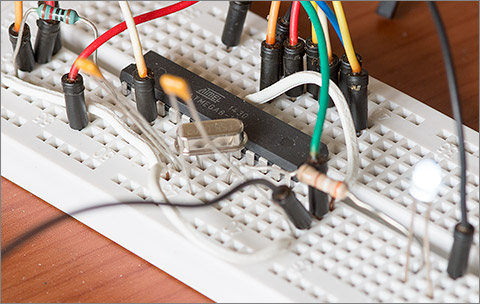
I was recently working on an all through-hole project and for prototyping purposes I’d bought myself an ATmega328P microcontroller from Farnell; you know the one, you can find it on every Arduino Uno board. The general idea was that I’d write the firmware with the luxury of 32Kb flash and then when I’d finished I’d downsize into the smallest MCU that it would fit in.

A somewhat battered and bent prototyping 328P
Squeezing the code
When I was done I had 37 classes divided into .h and .cpp files. The compiled firmware size was about 12Kb. The biggest single optimisation that you can make is to move all your method bodies into the header files and mark them with the inline linkage modifier. (Yes, it’s a linkage modifier and nothing else). Only the ISR entry points and any PROGMEM definitions should be left in the .cpp files.
With the entire code path visible to the optimiser it can really flex its muscles and the effect is dramatic. In my case the firmware shrank from 12Kb to 7Kb with avr-gcc 4.9.2. I could now fit it inside an ATmega8.
Sourcing an ATmega8
So off I go to the Farnell website to check out the prices. I always use Farnell. There’s free delivery on orders over £20 and I trust them to have a vetted supply chain. £2.39 + 20% VAT for a single ATmega8-16PU in the DIP package. Seems a lot to me, particularly when you can get a much faster and more capable STM32F0 for about a quid. And I didn’t have enough in my ever-growing shopping basket yet to hit the free delivery threshold.
Now I know that I always say that you have to be nuts to buy ICs direct from China via an auction site so colour me nuts but I had to have a look. ATmega8’s were available from sellers on Ali Express at the ridiculously cheap price of five for US$4.95. Less than a dollar each including shipping.

I just couldn’t resist it so I bought a pack and about two weeks later they arrived. Would they work? I don’t know. The internet is awash with tales of fake ICs from China with the most amusing one being the reel of bricks that the poor guys at Sparkfun bought. And then resold. Hmm, not sure that was a good idea.
A closer look
I wasn’t going to waste too much time testing these. If they didn’t work at the first attempt then they were going to get binned because my time is worth so much more than the difference between a dollar and the Farnell price. Out of curiosity the first thing I did was put one under the microscope to see if I could discern anything wrong with the case markings. Often the fakes have dodgy markings, sometimes even with spelling mistakes!
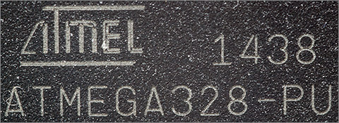
Here’s what my ATmega328P looks like under a 1:1 macro lens with 67mm of extension tubes.
Here’s what my potentially dodgy ATmega8 looks like under similar magnification. Note that the date codes are similar enough that you’d expect them to be produced using the same process.
Similar, but definitely not produced using the same machine. The etched logo on the 328P is created from two parallel marks and on the 8 it’s produced from 3 parallel marks.
Interestingly, and perhaps significant is that the ‘M’ in the Atmel logo on the 328P has a curve at the top right which matches the actual Atmel logo of a few years back. The ‘M’ on the Atmega8 has no such curve. Also note that the ‘L’ on the Atmega8 has an upward curve at the end that’s not present on the 328P and is not present in the genuine logo. Companies take great care with their logos and these could be the careless slips that identify the fake.
The blinky test
It’s surely the destiny of every ATmega MCU to blink a LED at some time in its life. It’s a good basic test and it will exercise the internal oscillator and one of the timer peripherals for just a few lines of code. This demo relies on the fuses to have been set so that the MCU runs at 8MHz. In my test I used an external crystal for that purpose.
Let’s take a look at the code. Firstly we need to use a timer to tick at millisecond resolution.
MillisecondTimer.h
#pragma once

/*
 * Use Timer0 to count in milliseconds
 */

class MillisecondTimer {

  public:
    static volatile uint32_t _counter;
    static volatile uint8_t _subCounter;

  public:
    static void setup();
    static uint32_t millis();
    static void delay(uint32_t waitfor);
};

/*
 * Setup timer 0. It will tick at 1MHz (CLK/8) and count 0-255 then generate an overflow
 * interrupt. So interrupt frequency = (CLK/8)*256 = 256uS. We will increment the millisecond
 * timer every 4 ticks = 1.024ms. Each interrupt we add 6 to the counter register which has the
 * effect of changing the interrupt frequency to (CLK/8)*250 and that gives us an accurate 1ms counter.
 */

inline void MillisecondTimer::setup() {

  // set up timer 0

  TCCR0 |= (1 << CS01);
  TIMSK |= (1 << TOIE0);
}

/*
 * Return the timer
 */

inline uint32_t MillisecondTimer::millis() {

  uint32_t ms;

  // an 8-bit MCU cannot atomically read/write a 32-bit value so we must
  // disable interrupts while retrieving the value to avoid getting a half-written
  // value if an interrupt gets in while we're reading it

  cli();
  ms=_counter;
  sei();

  return ms;
}

/*
 * Simple delay method
 */

inline void MillisecondTimer::delay(uint32_t waitfor) {

  uint32_t target;

  target=millis()+waitfor;
  while(_counter<target);
}
MillisecondTimer.cpp
#include <avr/io.h>
#include <avr/interrupt.h>
#include "MillisecondTimer.h"

volatile uint32_t MillisecondTimer::_counter=0;
volatile uint8_t MillisecondTimer::_subCounter=0;

/*
 * Timer 0 interrupt handler
 */

ISR(TIMER0_OVF_vect) {

  MillisecondTimer::_subCounter++;

  if((MillisecondTimer::_subCounter & 0x3)==0)
    MillisecondTimer::_counter++;

  TCNT0+=6;
}
Now that we’ve got the ability to take timings, I need a simple way to address the GPIO pins. Here’s how I do it efficiently. The templates and the typedefs give me readable code and the pure assembly language implementation ensures that it’s as efficient as possible.
GpioPin.h
#pragma once

/*
 * GPIO ports
 */

struct GPIOB {
  enum {
    Port = 0x18,
    Dir  = 0x17,
    Pin  = 0x16
  };
};

struct GPIOC {
  enum {
    Port = 0x15,
    Dir  = 0x14,
    Pin  = 0x13
  };
};

struct GPIOD {
  enum {
    Port = 0x12,
    Dir  = 0x11,
    Pin  = 0x10
  };
};

/*
 * Base template for all GPIO pins. Provide support for set/reset
 */

template<uint8_t TPort,uint8_t TPin>
struct GpioPin {

  static void set() {
    asm volatile(
      "  sbi  %[port],%[pin]  \n\t"
      :: [port] "I" (TPort),
         [pin]  "I" (TPin)
    );
  }

  static void reset() {
    asm volatile(
      "  cbi  %[port],%[pin]  \n\t"
      :: [port] "I" (TPort),
         [pin]  "I" (TPin)
    );
  }

  static void changeTo(bool state) {
    if(state)
      set();
    else
      reset();
  }
};

/*
 * GPIO output, provide support for init
 */

template<class TPort,uint8_t TPin>
struct GpioOutputPin : GpioPin<TPort::Port,TPin> {

  static void setup() {
    asm volatile(
      "  sbi  %[port],%[pin]  \n\t"
      :: [port] "I" (TPort::Dir),
         [pin]  "I" (TPin)
    );
  }
};

/*
 * GPIO input, provide support for init, read
 */

template<class TPort,uint8_t TPin>
struct GpioInputPin : GpioPin<TPort::Port,TPin> {

  static void setup() {
    asm volatile(
      "  cbi  %[port],%[pin]  \n\t"
      :: [port] "I" (TPort::Dir),
         [pin]  "I" (TPin)
    );
  }

  static bool read() {

    uint8_t r;

    asm volatile(
        "  clr  %[result]       \n\t"       // result = 0
        "  sbic %[port],%[pin]  \n\t"       // skip next if port bit is clear
        "  inc  %[result]       \n\t"       // result = 1
      : [result] "=r" (r)
      : [port]   "I"  (TPort::Pin),
        [pin]    "I"  (TPin)
    );

    return r;
  }
};


/*
 * All pins used in this project
 */

typedef GpioOutputPin<GPIOD,5> GpioLed;
With the plumbing now in place it’s a trivial matter to create the main method that does the blinking.
Blink.cpp
#include <avr/io.h>
#include <avr/interrupt.h>
#include "GpioPin.h"
#include "MillisecondTimer.h"

int main() {

  MillisecondTimer::setup();
  GpioLed::setup();     // PD5 (pin 11)

  sei();

  for(;;) {
    GpioLed::set();
    MillisecondTimer::delay(1000);

    GpioLed::reset();
    MillisecondTimer::delay(1000);
  }

  // not reached
  return 0;
}
The code’s written and now we need a way to build it. I use the scons build system because it’s based on Python which has the side effect of being a useful language. Here’s my SConstruct file. The upload target will use avrdude to upload the hex file to the MCU using a USBASP programmer and the fuse target will set the fuses to use an external crystal.
SConstruct
"""
Usage: scons [upload]

  [upload]
    specify this option to automatically upload to
    using avrdude to a USBASP connected MCU.

  To do a 'clean' use the -c flag
  To do a parallel build use the -jN flag
"""

import os

# source the environment

env=Environment(ENV=os.environ)

# compiler is avr-gcc

env.Replace(CC="avr-gcc")
env.Replace(CXX="avr-g++")
env.Replace(PROGSUFFIX=".elf")

# set up our options

env.Replace(CXXFLAGS=["-mmcu=atmega8",
                      "-Os",
                      "-g",
                      "-DF_CPU=8000000",
                      "-std=c++11",
                      "-Wall",
                      "-Werror",
                      "-Wextra",
                      "-pedantic-errors",
                      "-fno-rtti",
                      "-ffunction-sections",
                      "-fdata-sections",
                      "-fno-exceptions"])

env.Replace(LINKFLAGS=["-Wl,-Map,blink.map",
                       "-mrelax",
                       "-g",
                       "-Wl,--gc-sections",
                       "-mmcu=atmega8"])

# compile source code to .elf binary

elf=env.Program("blink",[Glob("*.cpp")])
Decider('timestamp-newer')

# convert elf to hex flashable image

env.Command("blink.hex",elf,"avr-objcopy -j .text -j .data -O ihex $SOURCE $TARGET")

# calculate size and generate assembly source

env.Command("blink.siz",elf,"avr-size $SOURCE | tee $TARGET")
env.Command("blink.lst",elf,"avr-objdump -S $SOURCE > $TARGET")

# upload target uses avrdude

flash_cmd="avrdude -c usbasp -p m8 -e -U flash:w:blink.hex"

# internal oscillator
#fuse_cmd="avrdude -c usbasp -p m8 -e -U lfuse:w:0xe4:m -U hfuse:w:0xd9:m"

# external crystal
fuse_cmd="avrdude -c usbasp -p m8 -e -U lfuse:w:0xff:m -U hfuse:w:0xd9:m"

upload=env.Alias("upload","blink.hex",flash_cmd)
fuse=env.Alias("fuse","blink.hex",fuse_cmd)

AlwaysBuild([upload,fuse])
The code upload was successful and it immediately started blinking at 1Hz, just as designed.

It’s alive!
This simple demo shows that the internal oscillator, the external crystal interface, GPIO port D, the internal memories and the timer0 peripheral are all working as they should.
Watch the video
I distilled all of the above into a video that you can watch if you’d like to see me checking out these ICs.
Click here to watch the video at the youtube website. You’ll get a better quality experience if you do that.
It seems to work…
I can’t find anything wrong with it. Why is it so cheap? I don’t know. Perhaps they’re just overstock from someone’s bigger order. Perhaps a batch was rejected by QC for some unknown reason that ordinary use at room temperature will never discover. As far as I’m concerned they’re good to use and I got a bargain. For once.
If you’d like to share your experience, good or bad, with cheap ICs from China then do please leave a comment below or drop by the forum and post your thoughts.


