


stm32plus 3.1.1: Supporting the STM32 VL Discovery
If you’ve been following the releases on my stm32plus github repo then you’ll already be aware that version 3.1.1 has been released. The main feature of this new release is support for the STM32 Medium Density Value Line devices, exemplified by the STM32 Value Line Discovery board from ST Micro.
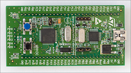
stm32plus has long supported the high density F103 and the powerful F4 series of MCUs and so I decided it was time to add support for the lower end devices that are cheap to buy and easy to work with. The F100 medium density (MD) value line (VL) devices come in configurations with up to 128Kb flash and 8Kb SRAM in packages as easy to work with as the LQFP48 (in my opinion anything with pins sticking out the sides is easy to work with by modern standards!)
Naturally, being a value line series the on-board peripherals are limited compared to the high-density and F4 series so many of the stm32plus examples are not available but the core peripherals such as the timers, USARTs and SPI are all present.
Building for the Medium Density Value Line
Assuming that you’ve downloaded and extracted the source code archive from github then you can build the library and all the compatible examples from a terminal prompt:
scons mode=debug mcu=f1mdvl hse=8000000 -j4
Some notes on the above command:
- You need to have installed
sconson your system. Consult your package management system for the exact installation syntax. On Ubuntu it would besudo apt-get install scons. - Windows users must use a Unix-alike subsystem such as Cygwin or msys. I use Cygwin on Windows 7 x64.
- Where I have used the
mode=debugoption I could also have usedsmallorfastmode options to build the library optimised for size or speed, respectively. - The parameter to the
-joption should reflect the number of cores in your build system.
OpenOCD and the ST-Link V1 debugger
Interactive debugging using the Eclipse CDT edition does not need any additional hardware because there is an ST-Link chip built on to the board.
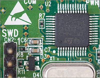
To drive the ST-Link you need to get a copy of the freeware OpenOCD utility. At the time of writing the latest version is 0.7.0 and the source can be downloaded from Sourceforge.
If you’re not interested in building from source then Linux users can install it using their package manager, e.g. for Ubuntu it would be sudo apt-get install openocd.
Windows users can download compiled binaries from this location.
OpenOCD runs in the foreground as a server process so you need to fire up a terminal window and run it with the appropriate options. I like to create trivial scripts that I can use to start OpenOCD on demand. For example, this is my script for Windows 7 x64 on Cygwin:
#!/bin/sh

cd openocd-0.7.0
bin-x64/openocd-x64-0.7.0.exe -f scripts/board/stm32vldiscovery.cfg
If it’s all working then you should see output like this when you run OpenOCD:
$ ./openocd-stlink-f1vl.sh
Open On-Chip Debugger 0.7.0 (2013-05-05-10:44)
Licensed under GNU GPL v2
For bug reports, read
        http://openocd.sourceforge.net/doc/doxygen/bugs.html
Info : This adapter doesn't support configurable speed
Info : STLINK v1 JTAG v11 API v2 SWIM v0 VID 0x0483 PID 0x3744
Info : stm32f1x.cpu: hardware has 6 breakpoints, 4 watchpoints
At this stage OpenOCD is running as a server and you can either telnet to it and issue direct commands or you can use Eclipse to flash the board and do some visual debugging. Let’s first look at directly sending commands to it using a telnet session.
Controlling OpenOCD with telnet
Here’s a log of a real telnet session to OpenOCD.
$ telnet localhost 4444
Trying 127.0.0.1...
Connected to localhost.
Escape character is '^]'.
Open On-Chip Debugger
> reset init
target state: halted
target halted due to debug-request, current mode: Thread
xPSR: 0x01000000 pc: 0x0801a5d8 msp: 0x20002000
> flash write_image erase p:/r61523_mdvl.hex
auto erase enabled
device id = 0x10016420
flash size = 128kbytes
wrote 117760 bytes from file p:/r61523_mdvl.hex in 13.424768s (8.566 KiB/s)
> reset
Let’s take a look at what’s going on here. Firstly I use telnet to establish a session with OpenOCD:
telnet localhost 4444
OpenOCD responds with a one-liner greeting and a simple > prompt. The first thing I need to do is to reset the board and halt it so that I can flash my program.
reset init
OpenOCD logs the fact that the MCU was reset and is now halted awaiting my next command. I will now flash the board with an ihex file that was produced when I built the stm32plus package and all its examples.
flash write_image erase p:/r61523_mdvl.hex
OpenOCD logs its progress and eventually tells me that it’s written 117760 bytes to the MCU. The device is still halted so now I’m going to reset it and this time let it go so my program will run.
reset
My program is running, and very pretty it is too even if I say so myself. That’s it down there towards the end of this article in the YouTube video.
Controlling OpenOCD with Eclipse
If you’re using Eclipse to do your development then you can have all the OpenOCD interaction automated by the gdb debugger and you’ll get visual debugging with breakpoints and variable/memory inspection. Pretty much everything you’d expect to get from a PC-based debugger.
Assuming that you’ve got a project that builds and produces a .elf file as its output, open the Run -> Debug Configurations form and create a new GDB Hardware Debugging configuration for your project.
All the important options are on the first three configuration tabs. Rather than list them all by rote I’ll show some screenshots of one of my configurations. It should be easy for you to adapt these details to your project:
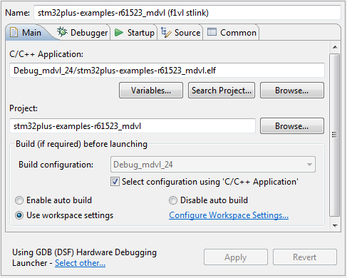
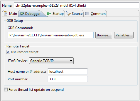
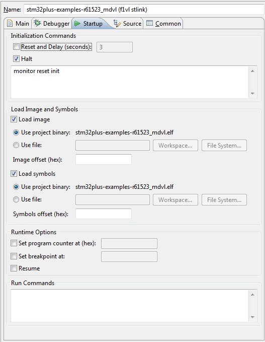
Now when I launch this configuration the latest build of the project will be automatically flashed to the board and it will reset and halt. I can then use the Resume Eclipse command to start the program.
Driving 16-bit LCDs
Support for many different LCD panel controllers is one of the main features of the stm32plus library so it’s only natural that I would look to provide support for the VL Discovery board. The MD VL range of MCUs does not have the FSMC peripheral that we often use to simplify access to an 8080-compatible LCD which means that we must do it with GPIO access.
Back in my reverse engineering the LG KF700 LCD article I presented an optimised GPIO access mode for the 72MHz STM32 F1 that used full GPIO port access to rapidly transfer 16-bits of data at a time. Naturally this is the method that I want to use on the VL discovery board because it will provide the fastest and most responsive user experience.
Unfortunately the VL Discovery board ships in a configuration that makes it impossible to access an entire port at once for IO because at least one of the pins on every available port is reconfigured for something other than IO.
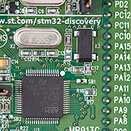
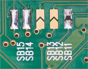
All is not lost however because ST have provided ways to reconfigure the board to get back some of those port pins if you don’t want the reconfigured functionality. In my example I will disable the external 32kHz oscillator designed to provide an accurate RTC clock and that will free up all of GPIO port C for IO. So warm up that soldering iron and here’s the modifications that you need to make to the board:
- Connect solder bridge SB14.
- Connect solder bridge SB15.
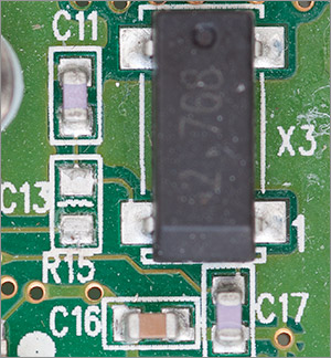
- Remove resistor R15 (it’s an 0R rating so not really a ‘resistor’). It’s a fairly small 0603 package and I had to use my hot air gun to get it off cleanly.
Here’s a picture of the connected solder bridges:
And here’s the empty space where R15 was before I removed it.
Creating the GPIO driver for my stm32plus open source library was quite straightforward because all I had to do was take the one that I created for the 72MHz F103 and remove all the delays because the maximum GPIO toggle speed on the F100 at 24MHz is 6Mhz. (2x clock cycles to go in one direction and 2x clock cycles to come back again). That’s actually 2MHz slower than the 16MHz Arduino.
The driver source code is available here on github, and a special stm32plus demo designed just for the VL discovery board and the 640×360 Sony Ericsson Vivaz U5 LCD is here.
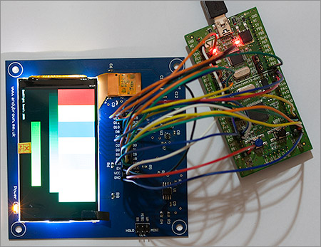
The overexposed still image shows the VL Discovery board hooked up to the LCD and playing the graphics library demo. The following video shows the whole demo running on the VL discovery board. As you can see the 6MHz GPIO speed is just about enough to provide a good user experience.
Final words
I’m happy with the support I’ve provided for the low end VL range. They provide a cheap and easy way into the ARM Cortex M3 family in packages and speeds that you might actually be able to work with successfully on your own PCBs.
Next off the production line from me will be support for the Cortex M0 ’51’ range (STM32F051) and I’m actually almost done bar a whole load of regression testing. At 48MHz the F0 outpaces the F1 VL range but there isn’t as much flash on offer, the peripherals are limited and the M0 core doesn’t have the full ‘thumb’ instruction set. Anyhow, I won’t spoil the fun, look out for a future article with the full details.