stm32plus: A full photoframe application

|
The code presented in this article requires a minimum of version 2.0.0 of my stm32plus library. |
About this article
For this next article in the series of stm32plus C++ demonstrations using the STM32F103 series of ARM Cortex M3 microcontrollers I thought that I’d take a break from showcasing LCD drivers and present a fully functional graphical photoframe application.
This one application will allow me to demonstrate several STM32 peripherals and capabilities in a series of upcoming articles. In particular, I will demonstrate:
- The 4-bit SDIO peripheral.
- FAT32/FAT16 file systems.
- Bitmaps.
- Fonts, proportional and fixed.
- Hardware LCD scrolling.
- Animation based on timers and interrupts.
The photoframe application
The goals of this simple application are as follows:
- Run on a QVGA (240×320) display. To save time we will only support the portrait orientation.
- Have a touch screen interface.
- Support hundreds of images.
- All transitions must be smooth to the eye and all graphical updates should be effectively instantaneous. Users today expect this level of responsiveness.
- Must not require any external memory or peripherals not included on the STM32F103.
- Must work on the lowest 72Mhz STM32 that sports the FSMC peripheral. This means the code and anything we compile in with it must fit into 128Kb of flash.
With all that lot in mind, let’s see how we get on.
Handling the graphics
Our primary (and indeed only) mass storage medium in this project is the SD card. Thankfully even the smallest cards these days have gigabytes of storage so no problems there.
Our app requires 240×320 images and 44×58 thumbnails in 18-bit (262K colours) format. Technically we could do the conversion from a format such as JPEG or PNG on the STM32 but that would be a waste of flash space when we’re going to be copying these across from the PC anyway. I do the resizing in Photoshop (which is overkill but I’m familiar with Photoshop) and stm32plus includes a format conversion utility.
The images below are a small selection of my own photographs that we’ll use in this demo.
[gallery_bank type=”images” format=”thumbnail” title=”false” desc=”false” responsive=”true” display=”all” sort_by=”pic_id” special_effect=”” animation_effect=”” album_title=”false” album_id=”2″]
The bm2rgbi utility
In the utils directory of the stm32plus package there is a PC utility bm2rgbi.exe. This utility will convert an image in any of the main formats (PNG, BMP, JPEG, GIF) to a format suitable for directly sending to the controller of an LCD panel supported by stm32plus.
Usage: bm2rgbi input-image-file output-image-file target-device target-colour-depth [-c]

-c : compress the output in LZG format
Supported devices and colours:
  ili9325 64
  ili9325 262
  ili9327 64
  ili9327 262
  ili9481 64
  ili9481 262
  hx8347a 64
  mc2pa8201 64
  mc2pa8201 262
  mc2pa8201 16
  lds285 64
  lds285 262
  lds285 16
Using the bm2rgi utility I created the necessary full size bitmaps and thumbnails from the resized images saved from Photoshop.
[insert pic of transfer process]
File system
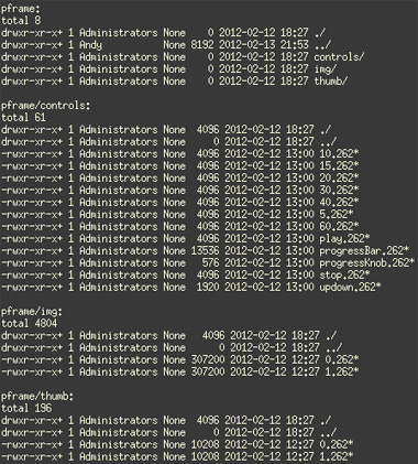
A screenshot of the file system on the SD card is shown below. The images are numbered sequentially from zero and stored in the img subdirectory. The corresponding thumbnails are named similarly and stored in the thumb subdirectory.

The filesystem on the card showing two images
The user interface is controlled by the touch screen on the LCD. When the user starts up the app for the first time the screen must be calibrated. stm32plus contains the routines for doing this, as demonstrated in my earlier article.
After calibration the calibration parameters are serialised to the SD card via an output stream attached to a file called ‘touchcal.bin’. Upon subsequent restarts of the application the calibration data is deserialised and the user is given five seconds to tap the screen if he wants to recalibrate.
High performance SDIO
We have a requirement for high performance. No-one is going to be impressed by images that visibly crawl down to fill the screen from the on-board storage. To achieve maximum performance we use a unique feature of the stm32plus FAT filesystem driver.
The stm32plus FAT file system driver contains a unique function that allows us to find a contiguous stretch of free blocks on the block device that the file system is created on (the SD card here). Since we are embedded and no-one else can pre-empt us and allocate this space to files we can use this free space as we see fit, and I’m going to use it as a fast cache for images.

Images are stored raw on the SD card without corrupting the file system
Reading blocks directly and sequentially from the device is much faster than having to deal with navigating the file system structure at the same time as reading the data. This feature is used by our app to create a cache of the images on startup in the unallocated space that can be dumped directly to the LCD on demand. Cool eh?
The main loop
During the main loop each image is read from the special cache described above and dumped to the LCD. We then pause for a configurable number of seconds before animating the transition to the next image using hardware scrolling. Hardware scrolling is a bit of an exaggeration on the part of the LCD controller manufacturers since all it does is change the position of scan line zero to somewhere other than the top but it does the job for us here.
Animation
stm32plus contains a number of animation transitions, known as easing functions, in the fx directory. Animation will be covered in a future blog article, for now you can see the bounce easing function in action in this application. The timing for the animation is controlled by a timer interrupt that triggers actions attached to a timeline.
Control GUI
Tapping the screen at any time gets you the control GUI. Using the GUI the user can go directly to any image using a scrolling windows of up to 8 thumbnails. These thumbnails are small graphic files so I don’t bother storing them in the free space image cache. They are opened and blitted in to the display interactively as the user uses the application.

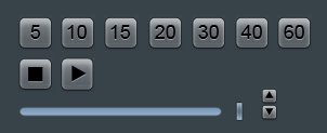
The controls used in the GUI
The control GUI also allows the user to configure the time between automatic image transitions using an up/down control (sometimes known as a spinner). The stop and play icons offer overall control over whether automatic image transitions are enabled at all.
All of the GUI elements in the control GUI, including each of the numeric ‘seconds’ indicators, were created in Photoshop before being resized down, converted with bm2rgbi and stored on the SD card. All I need to do at run-time is blit them into the display at the appropriate position at the right time.
Watch the video
Here’s a video that shows the app in action. As usual I can rely on my videography and post-production skills to make a slick application look completely terrible.
Get the source code
stm32plus contains the complete source code in the examples directory. it’s open source, have fun.


