


stm32plus: ILI9325 TFT driver

|
The code presented in this article requires a minimum of version 3.0.0 of my stm32plus library. |
The ILI9325 controller
This second article in the series of documentation-by-example posts will present a C++ driver for 320×240 (QVGA) TFT LCD panels that have an ILI9325 controller built in to them. This driver is included with my open source stm32plus C++ library and this article will show you how to use it with the STM32F103* ARM Cortex M3 microcontroller family running at 72Mhz. As of stm32plus 2.0.0 the driver is fully compatible with the STM32 F4 series of microcontrollers.
Updated sample code is available with stm32plus 3.0.0 or later and there’s a video hosted on YouTube that accompanies this article.
I like Ilitek controllers. They’re consistent across the range, they’re well documented and they’re easy to program if you’re familiar with TFT controllers, which I am.
The ILI9325 is a 320×240 (QVGA) device that supports 64K (5-6-5 RGB) or 262K (6-6-6 RGB). To the outside world (that’s us by the way) it presents 18-bit, 16-bit, SPI or a direct-drive RGB interface. It has its own onboard GRAM frame-buffer and expects you to send it commands that read and write from that buffer unless you’re in direct RGB mode in which case you are directly addressing the GRAM via a synchronised clock.
The panel
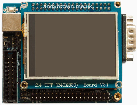
The 2.4″ TFT plays host to the ILI9325 controller, probably fitted COG-style.
Here’s the panel that I’ll be demonstrating. Mine happened to arrive as part of a “Mini STM32” development board that I got on ebay but they’re also available in various incarnations either ‘bare’ or pre-mounted on to a PCB that breaks out the controller pins for you.
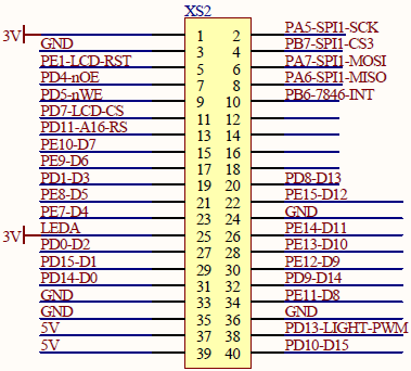
The pinout was documented as part of the overall schematic.
The schematic for the STM32 dev board documents the pinout for the TFT panel. Helpfully, the port numbers are annotated as well as the function of each pin. 16 data lines are broken out, so that implies we’re talking to the controller over its 16 bit bus (it has 18-bit, serial and RGB capabilities as well). Register-select (/RS), chip-select (CS), read (nOE) and write (nWE) are all there. There are additional pins for the reset line (RST) and the backlight. A pleasant surprise is the presence of the touch-screen interface on SPI1 up at the top right; we’ll be kicking the tires of the ADS7843 touch screen IC in a future article.

Here’s a tip for anyone who’s got this same dev board. The pins on the XS2 header are back-to-front on the schematic versus the board itself. That is, as you look down at the XS2 connector pins 3V is on the top right and PA5-SPI1-SCK is on the top left. 5V is on the bottom right and PD10-D15 is on the bottom left.
This dev board plays host to the STM32F103VET6 MCU. The V in ST’s nomenclature means that the device has 100 pins. Those of you that are familiar with the limitations of the 100 pin device will know that means that the Flexible Static Memory Controller (FSMC) only has one 64Mbyte NOR/SRAM bank at address 0x60000000. That’s fine, it gives me the chance to show stm32plus addressing a different bank than the usual #4 that I use on the STM32F103ZET6 board I use most often.
Since we’re using the FSMC, we need to choose an address line to attach to the RS line to control whether we are writing data or register selection to the controller. We’ll use line 16, resulting in the following addressing.
| Memory address | A16 line | transfer |
|---|---|---|
| 0x6000 0000 | 0 | register select |
| 0x6002 0000 | 1 | GRAM data |
stm32plus code
Here’s the code used to initialise the LCD. When this code has completed the LCD will be reset, initialised with your chosen colour mode, gamma and orientation and ready to use.
#include "config/stm32plus.h"
#include "config/display/tft.h"

using namespace stm32plus;
using namespace stm32plus::display;

/*
 * ILI9325 LCD test, show a looping graphics demo
 */

class ILI9325Test {

  protected:
    typedef Fsmc16BitAccessMode<FsmcBank1NorSram1> LcdAccessMode;
    typedef ILI9325_Portrait_262K<LcdAccessMode> LcdPanel;

    LcdAccessMode *_accessMode;
    LcdPanel *_gl;
    Font *_font;

  public:
    void run() {

      // reset is on PE1 and RS (D/CX) is on PD11

      GpioE<DefaultDigitalOutputFeature<1> > pe;
      GpioD<DefaultFsmcAlternateFunctionFeature<11>> pd;

      // set up the FSMC timing. these numbers (particularly the data
      // setup time) are dependent on both the FSMC bus speed and the
      // panel timing parameters.

      Fsmc8080LcdTiming fsmcTiming(0,2);

      // set up the FSMC with RS=A16 (PD11)

      _accessMode=new LcdAccessMode(fsmcTiming,16,pe[1]);
      _gl=new LcdPanel(*_accessMode);

      // apply gamma settings

      ILI9325Gamma gamma(0x0006,0x0101,0x0003,0x0106,0x0b02,
                         0x0302,0x0707,0x0007,0x0600,0x020b);
      _gl->applyGamma(gamma);

      // clear to black while the lights are out

      _gl->setBackground(0);
      _gl->clearScreen();

      // create the backlight on timer4, channel2 (PD13)

      DefaultBacklight backlight;

      // fade up to 100% in 4ms steps

      backlight.fadeTo(100,4);

      // create a font

      _font=new Font_VOLTER__28GOLDFISH_299;
      *_gl << *_font;
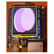
That’s all there is to it. If you’ve also read my previous article on driving the HX8347A controller then this will all look familiar. That’s because stm32plus hides away all the device-specific details and presents you with a unified interface for controlling graphic devices. Here’s a quickie image taken from the rolling demo. As usual the camera is less than kind to the TFT. The actual display is sharp and contrasty.
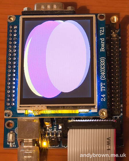
A freeze-frame from the rolling demo that shows the ILI9325 in 262K colour mode.
Let’s look at the code in a little more detail.
Includes and namespaces
#include "config/stm32plus.h"
#include "config/display/tft.h"

using namespace stm32plus;
using namespace stm32plus::display;
Firstly we need to include the headers that define the classes we’re going to use. Secondly, since all of stm32plus lives either in the stm32plus namespace or a sub-namespace (in this case stm32plus::display) we will import them into the global namespace to make the declarations of the objects less clumsy looking.
FSMC access mode and reset
  typedef Fsmc16BitAccessMode<FsmcBank1NorSram1> LcdAccessMode;
  typedef ILI9325_Portrait_262K<LcdAccessMode> LcdPanel;

  LcdAccessMode *_accessMode;
  LcdPanel *_gl;
  Font *_font;

public:
  void run() {

    // reset is on PE1 and RS (D/CX) is on PD11

    GpioE<DefaultDigitalOutputFeature<1> > pe;
    GpioD<DefaultFsmcAlternateFunctionFeature<11>> pd;

    // set up the FSMC timing. these numbers (particularly the data
    // setup time) are dependent on both the FSMC bus speed and the
    // panel timing parameters.

    Fsmc8080LcdTiming fsmcTiming(0,2);

    // set up the FSMC with RS=A16 (PD11)

    _accessMode=new LcdAccessMode(fsmcTiming,16,pe[1]);
We use an ‘access-mode’ class to control how we communicate with the panel. Here we initialise it to use the FSMC in 16-bit mode with A16 as the RS line (PD11). We will also be wiring up the panel’s RESET line to PE1.
We declare an Fsmc8080Lcdtiming object that takes care of the timing details. The two parameters are the address setup and data setup times in HCLK cycles. At full speed the STM32F1 has a 36MHz FSMC bus and the STM32F4 has a 60MHz bus. Therefore the timings may be different for each MCU if the bus is faster than the panel.
To determine the value of these parameters you need your panel’s data sheet and the equations in the ST Microelectronics application note AN2790 (google it). Alternatively you can just start with some large-ish numbers and decrease until the timings get too tight and the panel doesn’t respond!
Declare a panel
// declare a panel

_gl=new LcdPanel(*_accessMode);
Now that we have an access mode we can declare the panel. The constructor will ask the access mode class to reset the panel and then it will do the initialisation sequence.
Our example initialises it in portrait mode, 18 bit colour (262K). If you take a look at TftInterfaces.h you will see that following modes are available:
ILI9325_Portrait_262K
ILI9325_Landscape_262K
ILI9325_Portrait_64K
ILI9325_Landscape_64K
The predefined drivers are just C++ typedefs that bring together the necessary combination of template instantiations to create a coherent graphics library.
Gamma correction
// apply gamma settings

ILI9325Gamma gamma(0x0006,0x0101,0x0003,0x0106,0x0b02,
                   0x0302,0x0707,0x0007,0x0600,0x020b);
_gl->applyGamma(gamma);
Gamma correction involves the manual adjustment of the panel’s response to different shades of grey to compensate for differences in the manufacturing process. Every panel will be slightly different.
Setting up the tweaks to the gamma curve are optional, a reasonable display will be obtained by using the default linear curve but if true-to-life colours are a requirement then a custom gamma curve is essential.
stm32plus includes an interactive gamma adjustment application, and that will be introduced in a future blog post. For now, you can just use the default settings and maybe come back to it later.
Backlight
// create the backlight on timer4, channel2 (PD13)

DefaultBacklight backlight;

// fade up to 100% in 4ms steps

backlight.fadeTo(100,4);
stm32plus comes with a PWM backlight controller template class, and a subclass of that called DefaultBacklight that assumes you can connect the backlight regulator to PD13.
This PWM output should be used to drive the base of suitable transistor, or the ‘enable’ pin of a constant current backlight driver. It should not be used to directly power the backlight because it’s likely to draw too much current from the MCU pin.
The fadeTo method allows smooth transitioning of the backlight between levels to give a pleasing user experience.
Font selection
// create a font

_font=new Font_VOLTER__28GOLDFISH_299;
*_gl << *_font;
stm32plus (as of 1.2.0) now supports the very convenient stream ‘<<' operator to output text and numbers to the display. To do this the operator needs to know which font to use, and we do that by using the << operator with the font object as the operand.
stm32plus (as of 1.2.0) now supports the very convenient stream ‘<<' operator to output text and numbers to the display. To do this the operator needs to know which font to use, and we do that by using the << operator with the font object as the operand.
Demo code and video
The stm32plus package contains the full source code to the demo that you can see in the video below.
Visit youtube to view this video in high resolution
The clear screen demo shows that I can transfer data to this display in 262K colour mode at roughly 2.45 megapixels/second. This will vary per-display based on the specifications for the address and data setup time. If you need a super-fast display, always check out the timing specs in the datasheet before you buy.
More to come…
Watch this space for much more free stuff to come. ILI9327 and ILI9481 touch screens and more. It’s all here!
Download source code
The stm32plus source package is available from my downloads page.