


stm32f4discovery: Up and running with the ARM Cortex M4
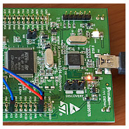
The stm32f4discovery is the ARM Cortex M4 evaluation board from ST Microelectronics. I’ve been following the progress of the Cortex M4 since its launch, looking for the right time to dip in give the new MCU a test drive.
That opportunity came with the launch of the stm32f4discovery board. I got mine from Farnell Electronics where, at the time of writing, they are on sale for £9.96 + VAT.
For just over a tenner you get rather a lot on board. To quote the good bits from the ST blurb:
- 168Mhz STM32F407VGT6 microcontroller featuring 32-bit ARM Cortex-M4F core, 1 MB Flash, 192 KB RAM in an LQFP100 package
- On-board ST-LINK/V2 with selection mode switch to use the kit as a standalone ST-LINK/V2 (with SWD connector for programming and debugging). Not sure about this one, JTAG is my tried and trusted debugging method, we’ll have to see what we can do with this.
- LIS302DL, ST MEMS motion sensor, 3-axis digital output accelerometer
- MP45DT02, ST MEMS audio sensor, omni-directional digital microphone
- CS43L22, audio DAC with integrated class D speaker driver
- Four user LEDs, LD3 (orange), LD4 (green), LD5 (red) and LD6 (blue)
- Two push buttons (user and reset)
- USB OTG FS with micro-AB connector
- Extension header for all LQFP100 I/Os for quick connection to prototyping board and easy probing
Setting up a free toolchain
This is going to be explained from the point-of-view of a windows user. Linux users should find the procedure broadly similar.
Here’s my workflow. I’m going to walk through the steps required to set up the whole thing.
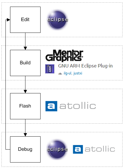
Eclipse
I do all my project editing in Eclipse. The current version of Eclipse is Indigo and it’s now fully compatible with the ARM toolchain plugin. Get Eclipse from here and make sure you download the edition for C++ developers (CDT).
The GNU ARM Eclipse plugin
Before you can get going with Eclipse you’re going to need the GNU ARM Eclipse plugin. Here’s the official site with instructions about how to install it.
Sourcery Codebench Lite Edition
This used to be called CodeSourcery but evidently they’ve been bought by Mentor Graphics and some re-branding has been going on.
Go to their site and download the latest EABI lite edition. This is the GNU GCC package set up for ARM cross-compilation.
stm32f4 peripheral library
It’s possible to develop applications for the STM32 without the peripheral library, and many people do just that. Me, I rather like it and clearly ST Microelectronics have put significant effort into making it work well. Click here to download the 31.5Mb package from the ST Microelectronics site.
Unzip the package and you’ll find the library in the LibrariesSTM32F4xx_StdPeriph_Driver folder.
CMSIS library
This one is supplied by ARM. It gives you functions for accessing the basics of the Cortex M4 that are the same across all manufacturers. It goes hand in hand with the standard peripheral library. You can find it in the same firmware zip as the standard peripheral library in the LibrariesCMSIS folder.
I make the following changes to CMSIS before using it.
- Exclude all of STSTM32F4xxSourceTemplates from any build. This folder contains example startup assembly code for different compilers. Instead of building this into CMSIS I take a copy of the correct startup source (the one in the TrueSTUDIO folder) and I add it to my project.
-
I prepend the following line to CMSISSTSTM32F4xxIncludestm32f4xx.h:
#define assert_param(a)((void)0)
This has the effect of disabling parameter validity checking in the peripheral library, something which I don’t want.
Atollic true stdio lite
The lite edition of this commercial package is available for free download. There are a couple of useful items in this package that we’ll take advantage of to get up and running. The linker (.ld) script will help us create a runnable image of our project and the GDB server will arbitrate our debug sessions between Eclipse and the ST-Link hardware.
Test Application
With all the tools in place I’m all set to create a test application. I decided to dive straight in and try driving one of the little Nokia 2730 QVGA LCDs that I’ve been tinkering with of late. After extracting the code from stm32plus and porting it to the F4 firmware library I came up with the following test code:
/*
* This file is a part of the open source stm32plus library.
* Copyright (c) 2012 Andy Brown <www.andybrown.me.uk>
* Please see website for licensing terms.
*/

#include <cstdlib>
#include "stm32f4xx.h"
#include "stm32f4xx_rcc.h"
#include "stm32f4xx_gpio.h"
#include "stm32f4xx_fsmc.h"

#define NOKIA_6300
#undef NOKIA_2730

// initialisation

static void initSystick();
static void initGPIO();
static void initFSMC();
static void initLCD();
static void checkWiring();

// demo

static void showDemo();
static void lineDemo();
static void rectDemo();

// timing

static void delayMillis(uint32_t timedelay);
static volatile uint32_t millisecondCounter;

// fsmc access

static void writeCommand(uint16_t command);
static void writeCommand(uint16_t command,uint16_t parameter);
static void writeData(uint16_t data);

static volatile uint16_t *fsmcData=reinterpret_cast<volatile uint16_t *>(0x60020000);
static volatile uint16_t *fsmcRegister=reinterpret_cast<volatile uint16_t *>(0x60000000);

// graphics operations

static void beginWriting();
static void moveTo(int16_t x1,int16_t y1,int16_t x2=239,int16_t y2=319);
static void clearScreen(uint8_t r,uint8_t g,uint8_t b);
static void drawLine(int16_t x1,int16_t y1,int16_t x2,int16_t y2,uint8_t r,uint8_t g,uint8_t b);
static void plotPoint(int16_t x,int16_t y,uint8_t r,uint8_t g,uint8_t b);
static void fillRectangle(int16_t x,int16_t y,int16_t width,int16_t height,uint8_t r,uint8_t g,uint8_t b);


/*
* The command set as documented in v0.99 of the MC2PA8201 datasheet
*/

enum E {
  NOP=0,
  SOFTWARE_RESET=1,
  READ_DISPLAY_ID=4,
  READ_DISPLAY_STATUS=9,
  READ_DISPLAY_POWER_MODE=0xA,
  READ_DISPLAY_MADCTL=0xb,
  READ_DISPLAY_PIXEL_FORMAT=0xc,
  READ_DISPLAY_IMAGE_MODE=0xd,
  READ_DISPLAY_SIGNAL_MODE=0xe,
  READ_DISPLAY_SELF_DIAGNOSTICS=0xf,
  SLEEP_IN=0x10,
  SLEEP_OUT=0x11,
  PARTIAL_MODE_ON=0x12,
  NORMAL_DISPLAY_MODE_ON=0x13,
  DISPLAY_INVERSION_OFF=0x20,
  DISPLAY_INVERSION_ON=0x21,
  GAMMA_SET=0x26,
  DISPLAY_OFF=0x28,
  DISPLAY_ON=0x29,
  COLUMN_ADDRESS_SET=0x2a,
  PAGE_ADDRESS_SET=0x2b,
  MEMORY_WRITE=0x2c,
  COLOUR_SET=0x2d,
  MEMORY_READ=0x2e,
  PARTIAL_AREA=0x30,
  VERTICAL_SCROLLING_DEFINITION=0x33,
  TEARING_EFFECT_LINE_OFF=0x34,
  TEARING_EFFECT_LINE_ON=0x35,
  MEMORY_ACCESS_CONTROL=0x36,
  VERTICAL_SCROLLING_START_ADDRESS=0x37,
  IDLE_MODE_OFF=0x38,
  IDLE_MODE_ON=0x39,
  INTERFACE_PIXEL_FORMAT=0x3a,
  READ_ID1=0xda,
  READ_ID2=0xdb,
  READ_ID3=0xdc
};


/*
* Main entry point
*/

int main(void) {

  // initialisations

  initSystick();
  initGPIO();
  initFSMC();
  initLCD();

  // run the demo

  checkWiring();
  showDemo();

  // not reached
  return 0;
}


/*
* Check wiring by reading the device code
*/

void checkWiring() {

  uint8_t data[4];
  int i;

  writeCommand(READ_DISPLAY_ID);

  for(i=0;i<4;i++)
    data[i]=*fsmcData;

  // check for the correct response and hangup if it's
  // not there

  if(data[1]!=0x54 || data[2]!=0x80)
    for(;;);
}


/*
* Run a basic demo
*/

void showDemo() {

  for(;;) {

    clearScreen(0x00,0x00,0x00);
    lineDemo();

    clearScreen(0x00,0x00,0x00);
    rectDemo();
  }
}


/*
* Clear down the screen
*/

void clearScreen(uint8_t r,uint8_t g,uint8_t b) {

  int32_t i;

  moveTo(0,0);
  beginWriting();

  i=320*240;
  while(i--) {
    *fsmcData=b;
    *fsmcData=g;
    *fsmcData=r;
  }
}


/*
* Run a demo drawing random coloured lines
*/

void lineDemo() {

  int16_t x1,y1,x2,y2;
  int i;
  uint32_t cr;

  for(i=0;i<5000;i++) {
    x1=rand() % 240;
    y1=rand() % 320;
    x2=rand() % 240;
    y2=rand() % 320;

    cr=rand();
    drawLine(x1,y1,x2,y2,(cr >> 16) & 0xfc,(cr >> 8 ) & 0xfc,cr & 0xfc);
  }
}


/*
* Show a rectangle demo
*/

void rectDemo() {

  int i;
  int16_t x,y,w,h;
  uint32_t cr;

  for(i=0;i<2000;i++) {

    x=(rand() % 240/2);
    y=(rand() % 320/2);
    w=rand() % (240-x);
    h=rand() % (320-y);

    cr=rand();
    fillRectangle(x,y,w,h,(cr >> 16) & 0xfc,(cr >> 8 ) & 0xfc,cr & 0xfc);
  }
}


/*
* Draw a line in the requested colour
*/

void drawLine(int16_t x1,int16_t y1,int16_t x2,int16_t y2,uint8_t r,uint8_t g,uint8_t b) {

  bool yLonger=false;
  int incrementVal,endVal;
  int shortLen=y2-y1;
  int longLen=x2-x1;

  if(abs(shortLen) > abs(longLen)) {
    int swap=shortLen;
    shortLen=longLen;
    longLen=swap;
    yLonger=true;
  }

  endVal=longLen;

  if(longLen < 0) {
    incrementVal=-1;
    longLen=-longLen;
    endVal--;
  } else {
    incrementVal=1;
    endVal++;
  }

  int decInc;

  if(longLen == 0)
    decInc=0;
  else
    decInc=(shortLen << 16) / longLen;

  int j=0;

  if(yLonger) {
    for(int i=0;i != endVal;i+=incrementVal) {
      plotPoint(x1 + (j >> 16),y1 + i,r,g,b);
      j+=decInc;
    }
  } else {
    for(int i=0;i != endVal;i+=incrementVal) {
      plotPoint(x1 + i,y1 + (j >> 16),r,g,b);
      j+=decInc;
    }
  }

}


/*
* plot a single point
*/

void plotPoint(int16_t x,int16_t y,uint8_t r,uint8_t g,uint8_t b) {

  // move to the point and start writing

  moveTo(x,y);
  beginWriting();

  // we set it up in BGR colour order

  writeData(b);
  writeData(g);
  writeData(r);
}


/*
* Fill a rectangle
*/

void fillRectangle(int16_t x,int16_t y,int16_t width,int16_t height,uint8_t r,uint8_t g,uint8_t b) {

  int32_t count;

  // number of pixels to fill

  count=width*height;

  // set the display window and prepare for writing

  moveTo(x,y,x+width-1,y+height-1);
  beginWriting();

  // blit the pixels

  while(count--) {
    *fsmcData=b;
    *fsmcData=g;
    *fsmcData=r;
  }
}


/*
* Begin writing
*/

void beginWriting() {
  writeCommand(MEMORY_WRITE);
}


/*
* Move to pixel position (or rectangle if x2 and y2 are specified)
*/

void moveTo(int16_t x1,int16_t y1,int16_t x2,int16_t y2) {

  writeCommand(COLUMN_ADDRESS_SET);

  writeData(0);								// x=0..239
  writeData(x1);
  writeData(0);
  writeData(x2);

  writeCommand(PAGE_ADDRESS_SET);

  writeData(y1 >> 8);					// y=0..319
  writeData(y1 & 0xff);
  writeData(y2 >> 8);
  writeData(y2 & 0xff);
}


/*
* Reset and initialise the LCD
*/

void initLCD() {

  // reset

  GPIO_ResetBits(GPIOE,GPIO_Pin_1);
  delayMillis(5);
  GPIO_SetBits(GPIOE,GPIO_Pin_1);
  delayMillis(10);

  // init sequence

  writeCommand(SLEEP_OUT);
  writeCommand(DISPLAY_INVERSION_OFF);
  writeCommand(IDLE_MODE_OFF);
  writeCommand(NORMAL_DISPLAY_MODE_ON);

  writeCommand(MEMORY_ACCESS_CONTROL,0xc8);			// BGR

  // wait

  delayMillis(125);

  // turn the display on

  writeCommand(DISPLAY_ON);

  // select 262K colour mode

  writeCommand(INTERFACE_PIXEL_FORMAT,0x66);
}


/*
* Write to the LCD
*/

void writeCommand(uint16_t reg,uint16_t data) {
  *fsmcRegister=reg;
  *fsmcData=data;
}

void writeCommand(uint16_t reg) {
  *fsmcRegister=reg;
}

void writeData(uint16_t data) {
  *fsmcData=data;
}


/*
* Initialise GPIO ports D and E for FSMC use
* Also initialise PE1 for RESET
* RS will be on A16
*/

void initGPIO() {

  GPIO_InitTypeDef init={0};

  RCC_AHB1PeriphClockCmd(RCC_AHB1Periph_GPIOD | RCC_AHB1Periph_GPIOE,ENABLE);

  // reset

  init.GPIO_Pin=GPIO_Pin_1;
  init.GPIO_Mode=GPIO_Mode_OUT;
  init.GPIO_Speed=GPIO_Speed_50MHz;

  GPIO_Init(GPIOE,&init);

  GPIO_PinAFConfig(GPIOD, GPIO_PinSource0, GPIO_AF_FSMC);			// D2
  GPIO_PinAFConfig(GPIOD, GPIO_PinSource1, GPIO_AF_FSMC);			// D3
  GPIO_PinAFConfig(GPIOD, GPIO_PinSource4, GPIO_AF_FSMC);			// NOE -> RD
  GPIO_PinAFConfig(GPIOD, GPIO_PinSource5, GPIO_AF_FSMC);			// NWE -> WR
  GPIO_PinAFConfig(GPIOD, GPIO_PinSource7, GPIO_AF_FSMC);			// NE1 -> CS
  GPIO_PinAFConfig(GPIOD, GPIO_PinSource8, GPIO_AF_FSMC);			// D13
  GPIO_PinAFConfig(GPIOD, GPIO_PinSource9, GPIO_AF_FSMC);			// D14
  GPIO_PinAFConfig(GPIOD, GPIO_PinSource10, GPIO_AF_FSMC);		// D15
  GPIO_PinAFConfig(GPIOD, GPIO_PinSource11, GPIO_AF_FSMC);		// A16 -> RS
  GPIO_PinAFConfig(GPIOD, GPIO_PinSource14, GPIO_AF_FSMC);		// D0
  GPIO_PinAFConfig(GPIOD, GPIO_PinSource15, GPIO_AF_FSMC);		// D1

  // PORTE

  GPIO_PinAFConfig(GPIOE, GPIO_PinSource7, GPIO_AF_FSMC);			// D4
  GPIO_PinAFConfig(GPIOE, GPIO_PinSource8, GPIO_AF_FSMC);			// D5
  GPIO_PinAFConfig(GPIOE, GPIO_PinSource9, GPIO_AF_FSMC);			// D6
  GPIO_PinAFConfig(GPIOE, GPIO_PinSource10, GPIO_AF_FSMC);		// D7
  GPIO_PinAFConfig(GPIOE, GPIO_PinSource11, GPIO_AF_FSMC);		// D8
  GPIO_PinAFConfig(GPIOE, GPIO_PinSource12, GPIO_AF_FSMC);		// D9
  GPIO_PinAFConfig(GPIOE, GPIO_PinSource13, GPIO_AF_FSMC);		// D10
  GPIO_PinAFConfig(GPIOE, GPIO_PinSource14, GPIO_AF_FSMC);		// D11
  GPIO_PinAFConfig(GPIOE, GPIO_PinSource15, GPIO_AF_FSMC);		// D12

  init.GPIO_Pin = GPIO_Pin_0 | GPIO_Pin_1 | GPIO_Pin_4 | GPIO_Pin_5 |
                                  GPIO_Pin_7 | GPIO_Pin_8 | GPIO_Pin_9 | GPIO_Pin_10 |
                                  GPIO_Pin_11 | GPIO_Pin_14 | GPIO_Pin_15;
  init.GPIO_Mode = GPIO_Mode_AF;
  init.GPIO_Speed = GPIO_Speed_100MHz;
  init.GPIO_OType = GPIO_OType_PP;
  init.GPIO_PuPd  = GPIO_PuPd_NOPULL;

  GPIO_Init(GPIOD, &init);

  // PORTE
  init.GPIO_Pin = GPIO_Pin_7 | GPIO_Pin_8 | GPIO_Pin_9 | GPIO_Pin_10 |
                                  GPIO_Pin_11 | GPIO_Pin_12 | GPIO_Pin_13 | GPIO_Pin_14 |
                                  GPIO_Pin_15;
  init.GPIO_Mode = GPIO_Mode_AF;
  init.GPIO_Speed = GPIO_Speed_100MHz;
  init.GPIO_OType = GPIO_OType_PP;
  init.GPIO_PuPd  = GPIO_PuPd_NOPULL;

  GPIO_Init(GPIOE, &init);
}


/*
* Initialise NOR/SRAM bank 1
*/

void initFSMC() {

  FSMC_NORSRAMTimingInitTypeDef timing={0};
  FSMC_NORSRAMInitTypeDef init={0};

  RCC_AHB3PeriphClockCmd(RCC_AHB3Periph_FSMC,ENABLE);

  timing.FSMC_AddressSetupTime=0;
  timing.FSMC_DataSetupTime=5;
  timing.FSMC_AccessMode=FSMC_AccessMode_A;
  timing.FSMC_CLKDivision=1;

  // initialise how the FSMC will work and then enable it

  init.FSMC_Bank=FSMC_Bank1_NORSRAM1;
  init.FSMC_DataAddressMux=FSMC_DataAddressMux_Disable;
  init.FSMC_MemoryType=FSMC_MemoryType_SRAM;
  init.FSMC_MemoryDataWidth=FSMC_MemoryDataWidth_16b;
  init.FSMC_BurstAccessMode=FSMC_BurstAccessMode_Disable;
  init.FSMC_WaitSignalPolarity=FSMC_WaitSignalPolarity_Low;
  init.FSMC_WrapMode=FSMC_WrapMode_Disable;
  init.FSMC_WaitSignalActive=FSMC_WaitSignalActive_BeforeWaitState;
  init.FSMC_WriteOperation=FSMC_WriteOperation_Enable;
  init.FSMC_WaitSignal=FSMC_WaitSignal_Disable;
  init.FSMC_ExtendedMode=FSMC_ExtendedMode_Disable;
  init.FSMC_WriteBurst=FSMC_WriteBurst_Disable;
  init.FSMC_ReadWriteTimingStruct=&timing;
  init.FSMC_WriteTimingStruct=&timing;
  init.FSMC_AsynchronousWait=FSMC_AsynchronousWait_Disable;

  FSMC_NORSRAMInit(&init);
  FSMC_NORSRAMCmd(FSMC_Bank1_NORSRAM1,ENABLE);
}


/*
* start counting millis
*/

void initSystick() {
  millisecondCounter=0;
  SysTick_Config(SystemCoreClock/1000);
}


/*
* Delay for the given milliseconds
*/

void delayMillis(uint32_t millis) {
  uint32_t target;

  target=millisecondCounter+millis;
  while(millisecondCounter<target)
    ;
}


/*
* SysTick interrupt handler
*/

extern "C" {
  void SysTick_Handler(void) {
    millisecondCounter++;
  }
}
This example application will run a continuous loop showing random coloured lines being drawn followed by random sized and coloured rectangles.
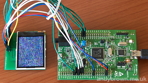
The test application
Flashing and debugging the compiled code
Traditionally this is the part that causes the most trouble for developers, probably because it’s the first time in the development cycle that we have to work with the actual hardware.
The stm32f4discovery board comes with ST’s proprietary debugging hardware ST-Link built in. ST-Link offers the advantage of using far fewer pins than the traditional JTAG connector but the downside is that the Serial Wire Debug (SWD) protocol that it uses does not enjoy the same support as JTAG in the open source community.
OpenOCD ST-Link support is not quite there
I checked out the latest openocd source code, compiled it up and tested it against the stm32f4discovery board. Within a few minutes I was able to use openocd to flash my code to the board and it looked like debugging was working too.
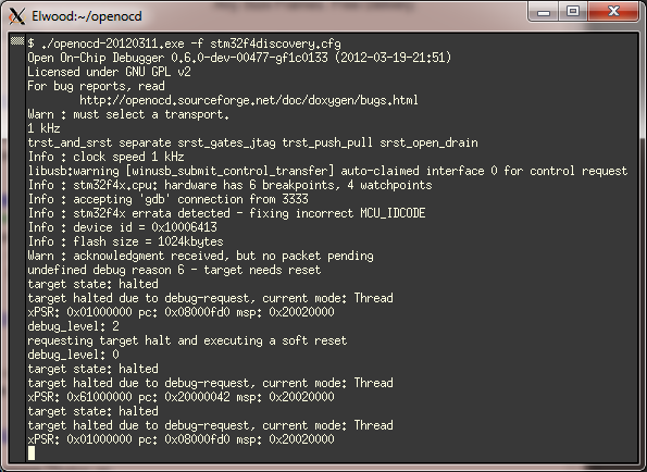
First startup is encouraging. The debugger flashes the image and connects for a debug session.
Unfortunately debugging was not working well enough for me to consider it as suitable for regular development. After reset I could connect Eclipse to openocd and a debug session was established.
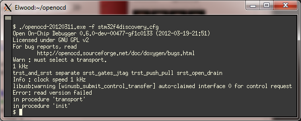
Unfortunately it all too often ends up like this.
Sadly though, this only lasted for the single session. When I made changes to my code and reflashed it was as though the debugger did not see the code change and the program crashed. The only way to get it working again was to power-cycle the board and restart openocd. Having to do this each time I want to debug is not good enough, so I had to try another option.
Atollic GDB server
This one worked better than openocd in that I can do multiple repeated debug sessions without having to power-cycle the board. However I do have to Ctrl-C and restart the server before each debug session. This isn’t ideal but it’s just a minor inconvenience and doesn’t stand in the way of productive development.
The GDB server in the Atollic distribution is almost ready to use out of the box. Here’s how to get it going.
- Make sure your board is connected via the USB port and that the ST-Link drivers have been installed so that it shows up as a named device in your computer’s device manager.
- Fire up cygwin or a command prompt and change directory to your PC’s equivalent of C:\Program Files (x86)\Atollic\TrueSTUDIO for ARM Lite 3.0.0\Servers\ST-LINK_gdbserver
- Edit config.txt and towards the bottom of the file make sure the ‘-d’ option is enabled. By default it’s documented in there but not enabled. The -d option enables the SWD protocol. Without it the gdb server will not see the board.
- Fire up the server with ST-LINK_gdbserver.exe -c config.txt
If you got it right then the server should now be waiting for commands from Eclipse.
Debugging with Eclipse
The Eclipse hardware debugging facility gives you the ability to visually step through the code running on the device, set breakpoints and inspect variables and memory. Absolutely vital in my opinion and something that anyone who develops on a full size computer will expect as a matter of course.
When creating a debug launch configuration you need to specify a valid initialisation sequence. Here’s mine:
target remote localhost:61234
monitor reset init
monitor debug_level 2
monitor soft_reset_halt
set mem inaccessible-by-default off
monitor debug_level 0
file c:/users/andy/src/stm32f407test/Debug/stm32f407test.elf
load
monitor reset init
Watch the demo video
Here’s a demo giving a brief tour around the development board. The main components are highlighted and you can see the Nokia LCD getting a workout.
stm32plus for the Cortex m4?
Yes, at long last it’s here.