


Reverse engineering the Nokia 2730 QVGA LCD
You may have noticed that I have a bit of a ‘thing’ for the little TFT displays that you can commonly get on ebay. There’s something satisfying about writing your own driver code and seeing one of these little panels come alive with your graphics.
Why the 2730 LCD?
- It’s high resolution (320×240, 200ppi) which means that graphics will look good.
- It’s used in a lot of models: Nokia 5000, 2730, 5130, 5220, 7100. Good for availability.
- It’s cheap, as low as £3.99 on ebay.
- It supports 262K (18-bit) colour mode.
- It looks like I can find the connector for it. Don’t underestimate the difficulty of this!
- The 24-pin connector has too few pins to be a direct drive LCD. That means it has a controller with embedded display RAM that I hope I can program.
- The service schematics give away the connector pinout. It’s definitely a controller and not direct drive.
Where do you start?
I started by getting a second-hand 2730 off ebay for less than 30 pounds. I had some vague notion that I’d be able to hook up my Ant18e logic analyser to the display connector to analyse the conversation between the phone’s MCU and the display.
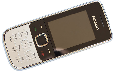
The Nokia 2730 I bought on ebay
That hope was scotched pretty quickly. There’s no way I can get probes on to the connector pins. I don’t know what I was thinking. Never mind, it’s not a bad phone and I might actually keep it as a backup.
While I had the phone in bits I was able to examine the connector mounted to the FPC. It’s a 24-pin 0.4mm pitch board-to-board connector that I have not yet been able to positively identify.
There are no markings on it and it ‘looks like’ a lot of products from Hirose, Molex, Kyocera and others. The problem with ‘looking like’ is that the differences between these parts is in the 0.1mm range and I know from some speculative purchases that if you get the wrong one then it just doesn’t mate.
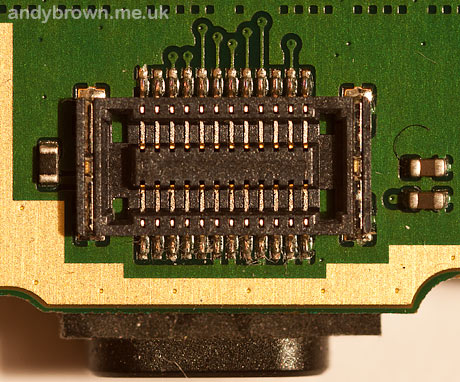
The connector on the phone pcb
When attempting to reverse engineer these connectors look for short traces that run directly to a plane. These are guaranteed to be ground connections.
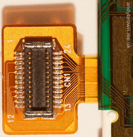
The connector on the LCD FPC cable
Fortunately I was able to source a handful of the board-side of these connectors from an online phone parts store. Still no clue as to the manufacturer though, and I’d like to hear from anyone who knows for sure what they are.
Known sources for the connector
It seems like there is considerable interest in sources for the 24 pin connector. I still don’t know who the OEM is. I’d suspect Hirose as they have past form in supplying Nokia connectors but I’ve been through their online catalogue with a magnifying glass and it’s not any one of the current production lines. Here are some links to online stores that have been found to sell the connector:
Examining the schematic
Nokia schematic RM-578 and RM-579 for the 2730 is available for download on the internet. I get the feeling from the copyright notices on the document that it was not meant to be publicly available so I will not host it on my site.
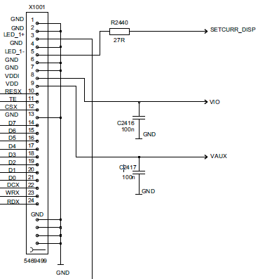
The connector schematic
There are a number of key facts that I can deduce from the schematic.
- The interface to the controller is 8-bit. That means 3 transfers per pixel for the 262K colour mode supported by the 2730 phone. That’s quite expensive but certainly workable.
- The control lines indicate that it’s either 8080 or 6800 protocol. The world at large seems to prefer 8080 so I’m going to guess that’s what this one uses.
- The backlight comprises of 4 white LEDs in series and I can see there’s a step-up DC-DC converter that looks like a constant current LED driver.
For those not familiar with the 8080 protocol here’s what the signals mean.
| D0-D7 | The data lines. In this implementation 8 bits are transferred in one transaction. |
| CSX | Chip select. Active low. Can be tied low if there’s nothing else sharing these lines. |
| DCX | Data/command select. Set high when transferring graphic data or parameters to commands. Set low when transferring a command (register) number. |
| WRX | Write enable. Data is transferred from D0-D7 to the controller on the rising edge of this signal. |
| RDX | Read enable. Data is transferred from the controller to D0-D7 on the rising edge of this signal. Can be tied high if reading is not required. |
| RESX | Hardware reset. Active low. The datasheet for the controller will specify minimum timings for the reset sequence. |
| TE | Tearing effect. This is a pin that the MCU reads from in order to synchronise writing to graphic RAM with the display refresh. An MCU that can refresh the display faster than the frame rate could cause strange ‘tearing effects’ in animation if it is not synchronized with this signal. |
Building a development board
Using the information gleaned so far I came up with the schematic for a basic development board that should work with my STM32.
The constant current LED driver is an OnSemi NCP5007 designed for powering up to 5 white LEDs in series. The circuit is straight from the datasheet and the feedback resistor is chosen to be 10Ω which gives a current of 20mA.
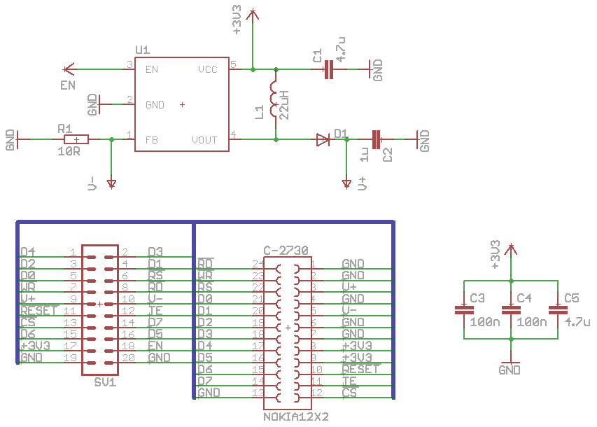
The Eagle schematic (click for larger)
The output capacitor, C2, needs to have a voltage rating higher than the maximum the IC can supply (which is 22V) to protect it in the case of an open circuit. The inductor L1 must have a self-resonant frequency above 1Mhz because the NCP5007 operates at 1Mhz. So the full parts list is:
| Name | Part | Package |
|---|---|---|
| U1 | OnSemi NCP5007 | SOT23-5 |
| L1 | 22µH inductor | 1212 |
| D1 | Schottky Diode | DO214AC |
| C1,C5 | 4.7µF capacitors | 0805 |
| C2 | 1µF 50V output capacitor | 0805 |
| C3,C4 | 100nF capacitors | 0603 |
| SV1 | 10×2 header | 2.54mm male |
| C-2730 | 12×2 receptacle | 0.4mm Nokia (please see comments at the bottom of this post for links to known supplier) |
I hand-routed the traces and designed it so that the FPC cable from the 24-pin connector would wrap-around the board so that the LCD could be mounted on the opposite side to the LED driver components, with the 2.54mm MCU interface pins sticking up next to it.
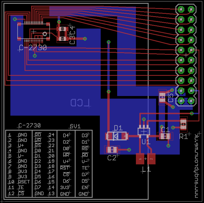
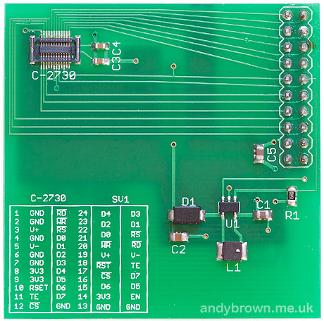
The Eagle PCB layout (click for larger)
The datasheet for the NCP5007 is pretty clear that you can’t just throw together the components and get optimal noise-free operation of the step-up converter. Care needs to be taken to minimise trace lengths and ideally ground and power planes should be used to reduce noise. I placed the components as close to each other as I dare and also used ground and power planes on the bottom layer.
The eagle Gerber CAD files were sent off to ITead Studios for manufacturing and two weeks later (yes, patience is a virtue, especially when the Chinese are out celebrating their new year) they were delivered.
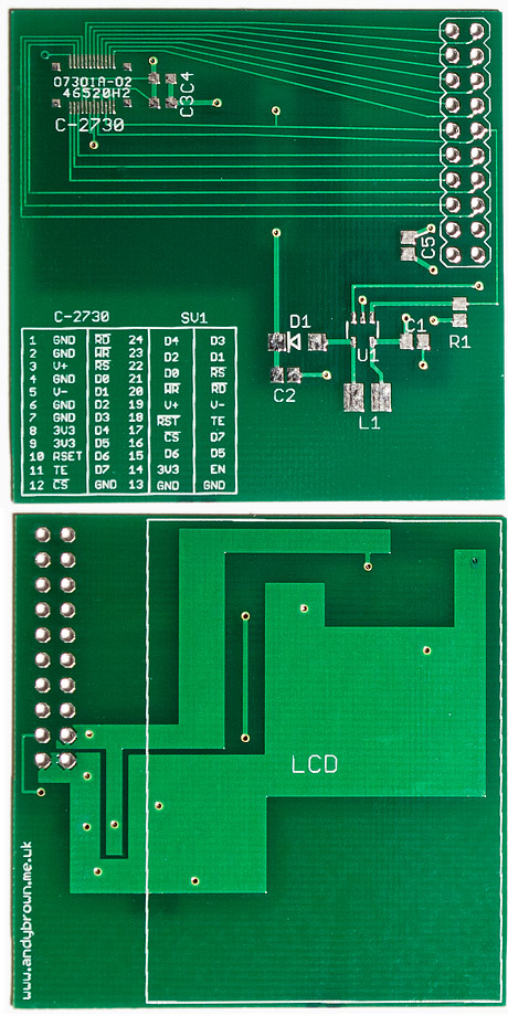
The bare PCB, front and back
Note the horrendously fine 0.4mm pitch connector footprint up the top left. The footprint design includes the four ‘posts’ around the corners that help to hold the connector securely to the board. The two 100nF decoupling capacitors next to it are in a fiddly small 0603 package. I chose this size to minimise the chance of them interfering with the FPC connector when it’s pressed down into the board receptacle.
After reflow and cleaning
My favoured method of mounting SMT components these days is to tin the pads with ordinary solder so you get little bumps, then liberally apply a paste flux and use it as a glue in which to position the SMD components. I then reflow the board carefully on a hot-plate.
Generally this works well, particularly with the large multi-pin ICs and connectors. They tend to just sit down nicely when the solder reflows. The smaller passive components such as the capacitors and resistors have a habit of sliding off their bumps before the solder has reflowed. I correct this at the time with a little nudge or afterwards with my heat gun.
The 2.54mm connector is hand-soldered after the SMD components have been reflowed.
The V+ and V- pins are not normally connected. They are used to test the backlight driver by connecting it up to an external LED string. i.e. you can connect V+ to the anode of LED1 and chain a further 3 LEDs anode-to-cathode with the final cathode going back to V-.
The EN pin is used to control the backlight. It is active HIGH. Applying a PWM signal to this pin will control the brightness of the backlight.
Blue smoke?
Lets hope not. The issue at stake is whether the controller can take the 3.3V from my STM32 on both VIO and VDD, with VDD being the logic interface that is often driven at 2.8V or even 1.8V by a phone. Every controller datasheet that I have is clear that 3.3V is in range for VDD but we don’t know what this is so this is going to be a nervous power-on.
Whatever you do, do not connect this circuit directly to a device with 5V levels such as the Arduino. The inputs and voltages are not 5V tolerant. An Arduino could be used to interface with this LCD with the addition of a level converter.
Well I’ll be, it works!
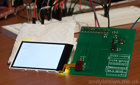
So far so good. No reason to get too excited though, in the above photograph all that I’ve done is test that the backlight circuit works and that the LCD powers up. Clearly it’s working so far.
You can also see four white LEDs wired in series in a breadboard behind the LCD. I used this LED string to test the output of the constant current driver before actually connecting the LCD. That’s why my development board exposes the V+ and V- output and feedback pins from the LED driver.
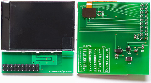
The dev board, front and back.
With the LCD mated snugly to the development board using double-sided sticky pads that keep it clear of the traces on the back of the PCB we’re ready to start reverse engineering the bus protocol.
Interrogating the controller
Most controllers have a register that allows you to read back information about the device and manufacturer. This will yield vital clues as to the controller’s identity. I wrote a quick program to read back 8 bytes from each of the controller’s registers. Most of them will be write-only and won’t tickle the bus but the ones that do will tell us vital information about the controller.
Here’s the output from that program. The first column is the register index, the next 8 bytes are the data response. I’ve stripped registers that return just zeros.
04 00 54 80 00 00 00 00 00
09 00 00 61 00 00 00 00 00
0a 08 08 08 08 08 08 08 08
0c 06 06 06 06 06 06 06 06
26 01 01 01 01 01 01 01 01
2a 00 00 00 00 ef 00 00 00
2b 00 00 00 01 3f 00 00 00
2e 00 80 bc b0 f8 00 f8 a4
30 00 00 00 01 3f 00 00 00
33 00 00 00 01 40 00 00 00
3a 00 06 00 00 00 00 00 00
6a ff ff ff ff ff ff ff ff
a1 00 54 80 00 0d 03 01 ff
a8 00 00 54 80 00 0d 03 01
da 54 54 54 54 54 54 54 54
db 80 80 80 80 80 80 80 80
Right away we’re on to something. Trawling through my collection of datasheets for TFTs I can see that the Leadis LDS285 uses 04h as its read device identifier (RDDID) code. The first byte returned by these controllers is always a dummy read, the real data is the values 54h and 80h, with 54h being the manufacturer code.
A quick search of the online list of MIPI manufacturer ids shows that 54h belongs to Arasan Chip Systems, Inc. Arasan is not a familiar name to me but their website reveals that they are engaged in making vertically integrated MIPI chipsets, i.e. the LCD controller, camera, file system etc. that you’d need if you were building a phone. The worrying news is that Leadis, whom we suspect of being the controller manufacturer have gone bust. I’m guessing that there is some kind of licensing agreement going on whereby Arasan and Leadis have collaborated to create an integrated controller.
Back to the device output, there is more evidence to support our theory that we’re looking at either an LDS285 or something that’s command-compatible with it. The datasheet states that commands DAh and DBh return the two identifier codes, and we can see that in the output.
More evidence in our favour is that registers 2Ah and 2Bh hold the column and row address start and end values. 0..239 and 0..319. The values that we see match. This is looking good.
Some random googling shows that there is someone else who’s experimented with LCDs from similar models to this one and determined that they tend to be command-compatible with a controller called the Magnachip MC2PA8201. This controller is itself a cut-down version of the LDS285. I’m going to assume that this is the one and see how far I get. Now it’s time to write an stm32plus driver for it and see if we can it to work!
Success!
After much experimentation I’ve determined the following about the LCD in the 2730:
- The controller is documented to support colour depths up to 24-bit but this LCD will not go higher than 262K colours. Attempts to use 24-bit mode results in display corruption. This is not surprising given that the phone specifications are for a 262K colour display. Colours transferred in 262K mode must have their lower 2-bits zeroed.
- 262K colours (3 transfers per pixel) and 64K colours (2 transfers per pixel) work perfectly. There are lower colour depths documented but I’m not concerned with them. I believe “an exercise for the reader” is the usual excuse wheeled out at this juncture.
- Hardware scrolling is supported.
- Portrait and landscape modes are supported and you can choose the orientation of each mode to suit which way up you’re mounting the LCD.
- Low power (sleep) mode works.
- Four gamma curve configurations are supported. My experimentation shows that the default gamma is probably the best.
- Either some of the colours are verboten or this cheap LCD has problems with a very small subset of colours. Very rarely an attempt to write a run of a certain solid colour will result in weird corruption. This is odd because adjusting the colour by only 1-bit will correct the problem.
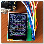
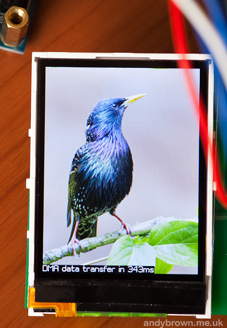
Here’s a few photographs of the LCD in action.
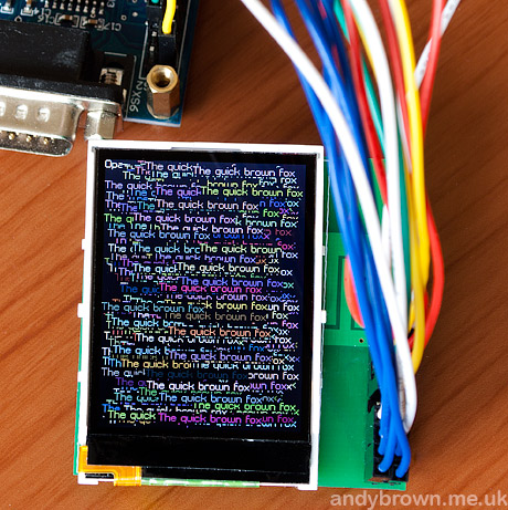
Testing the LCD
As usual the sensor in the digital camera fails to capture just how pin-sharp the little LCD appears to the human eye.
Displaying a bitmap
Watch the demo video
stm32plus 1.1.2 comes with drivers for the 64K and 262K colour modes for this LCD. You can see my usual demo sequence that exercises the capabilities of both the LCD and my graphics library in the video below.
Initialisation sequence
The key to getting any of these TFT devices up and running is the initialisation sequence, i.e. what you have to do after power-on in order to get the display powered up and ready for commands. To help you on the way, this is the basic sequence for this controller. The extract is from the stm32plus driver, but the code should be self-explanatory.
// reset the LCD

resetPin.reset();
MillisecondTimer::delay(5);
resetPin.set();
MillisecondTimer::delay(10);

// send the init sequence

writeCommand(SLEEP_OUT);
writeCommand(DISPLAY_INVERSION_OFF);
writeCommand(IDLE_MODE_OFF);
writeCommand(NORMAL_DISPLAY_MODE_ON);

if(_orientation==Orientation::Portrait)
  writeCommand(MEMORY_ACCESS_CONTROL,0xc8);     // BGR
else
  writeCommand(MEMORY_ACCESS_CONTROL,0xa8);     // BGR and horiz

// wait

MillisecondTimer::delay(125);

// turn the display on

writeCommand(DISPLAY_ON);
Drawing on the LCD
Drawing on these devices requires a fairly common set of operations. Firstly you move the drawing window to define a rectangle whose top left is at the first point you want to draw, then you send as many pixels to the display as you need.
If you send just one pixel then you get a single point at the top left of your drawing window and you can then move the window for the next point. This is useful for complex objects. Here’s a code sample for moving the drawing window to a point and extending the window from that point to fill the rest of the display.
    void moveTo(int16_t x,int16_t y) {

      _xpos=x;
      _ypos=y;

      writeCommand(COLUMN_ADDRESS_SET);

      if(_orientation==Orientation::Portrait) {

        writeData(0);               // x=0..239
        writeData(x);
        writeData(0);
        writeData(0xef);
      }
      else {

        writeData(x >> 8);          // x=0..319
        writeData(x & 0xff);
        writeData(1);
        writeData(0x3f);
      }

      writeCommand(PAGE_ADDRESS_SET);

      if(_orientation==Orientation::Portrait) {

        writeData(y >> 8);          // y=0..319
        writeData(y & 0xff);
        writeData(1);
        writeData(0x3f);
      }
      else {

        writeData(0);               // y=0..239
        writeData(y);
        writeData(0);
        writeData(0xef);
      }
    }
If you can divide your drawing requirements into discreet rectangles then it is far more efficient to send a command that defines the drawing window to match that rectangle and then repeatedly send pixels until the rectangle is filled. This is the approach taken by many of the algorithms in the stm32plus graphics library.
Schematic, CAD and gerbers available
You can now download the Eagle schematic, PCB artwork and Gerber files for this development board from my downloads page.