


stm32plus: ADS7843 touch screen driver

|
The code presented in this article requires a minimum of version 3.0.0 of my stm32plus library. |
The ADS7843
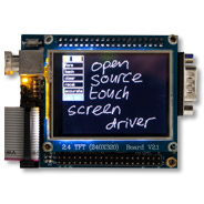
My last few blog articles have presented stm32plus drivers for the HX8347A and ILI9325 controllers. Given that both of these panels came with touch screens I think it’s about time that we took a brief interlude from the TFT drivers and presented a flexible touch screen driver for ADS7843-compatible controllers. This driver will feature pluggable noise-reduction and screen calibration implementation and I supply an advanced 3-point calibration algorithm and a variable strength pixel averaging noise reduction algorithm with the package.
The ADS7843 by Texas Instruments is the de-facto standard for cheap resistive touch screens. There are many compatible devices from other manufacturers available, such as the UH7843 by Zilltek and the XPT2046 by XPTEK. Both of these are 100% compatible with the ADS7843.
The ADS7843 is an analogue-to-digital converter and you can read up on the theory of operation in the datasheet. What we need to know is how we can talk to it.
The two basic parts to the ADS7843 digital interface are an SPI-compatible bus for transferring data and a single digital line (/PENIRQ) that the device pulls low when the the user touches the screen.
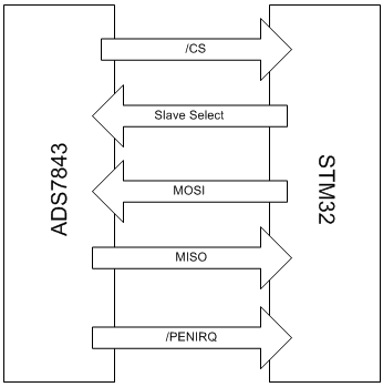
The SPI interface plus the PENIRQ line
The SPI protocol supported by the ADS7843 is straightforward. Basically you send it an 8-bit command that tells it whether you want to read X or Y, the resolution (8 or 12 bit), whether power-saving mode is to be enabled and a few other flags that affect the conversion.

The SPI protocol. Click for larger.
Note that in the timing diagram there is the presence of a BUSY line. Although this is provided we never use it because it is completely predictable in that it will be high for exactly one clock during the output cycle and it’s always the first clock. We compensate for this in software by throwing away the first bit received over the SPI bus.
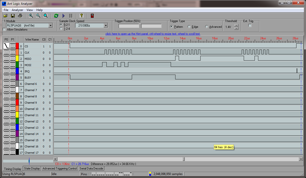
Click image for larger.
The screen grab above from my logic analyser shows the theory put into practice with a real life SPI conversation.
Interference and other issues
To be honest when I got started on this I took one look at the digital interface and thought: “No problem, I’ll be done in a few hours”. I look back and laugh at that now! The basic problem is that the data read from the AD converter is very noisy and we have to go to great lengths to smooth it out in order to get an accurate reading. Here’s a summary of the issues I found and how I got around them.
-
The first sample read from the panel after an interrupt is the worst quality.
This is because the screen has not settled yet. I throw away the first sample and keep the device in power-up mode while looping for subsequent samples.
-
The rest of the samples have much variance.
Keeping the device on, I oversample 7 times and choose the median using an optimised median algorithm.
-
Repeated samples still deviate slightly from each other.
I implemented a pluggable sample post-processor architecture. Adding an averaging post-processor reduces response times slightly but yields consecutive screen samples that differ by only fractions of a percent.
-
High-speed SPI means noisy samples.
I found that I get an optimal noise/speed tradeoff around 1 or 2Mhz for the SPI bus. What works for you may vary and stm32plus leaves this frequency up to you.
There is a great application bulletin PDF published originally by Burr Brown and subsequently by TI called “Touch Screen Controller Tips”. Most of the noise issues that I came up against are worked through in this paper. It’s a great read and comes highly recommended.
stm32plus implementation
The following diagram shows the basic program flow that happens when we interact with the touch screen.
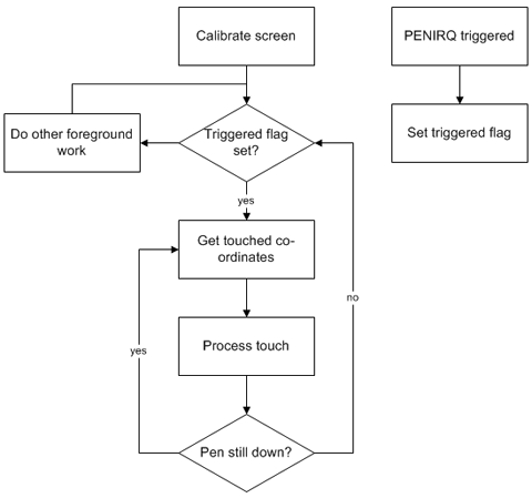
Basic high-level program flow
Watch the demo video
Click to watch in HD at Youtube
Source code
Here’s the corresponding code. This is taken from the stm32plus demo and cut down to show only the interaction with the touch screen.
#include "config/stm32plus.h"
#include "config/display/tft.h"
#include "config/display/touch.h"

using namespace stm32plus;
using namespace stm32plus::display;

/*
 * ADS7843 touch screen test - stripped down to show
 * only touch screen interaction.
 */

class ADS7843Test : public ThreePointTouchScreenCalibrator::GuiCallback {

  protected:
    // the touch screen object
    ADS7843AsyncTouchScreen *_touchScreen;

    // A SPI peripheral for talking to the touch screen
    Spi *_spi;

    // An EXTI interrupt line for the pen IRQ
    ExtiBase *_exti;

    // The GPIO pin corresponding to the pen IRQ
    GpioPinRef _penIrqPin;

    // calibrator and error-correction post-processors

    PassThroughTouchScreenCalibration *_passThroughCalibration;
    AveragingTouchScreenPostProcessor *_averagingPostProcessor;
    PassThroughTouchScreenPostProcessor *_passThroughPostProcessor;

    // the observer implementation will set this when the interrupt fires

    volatile bool _clicked;

  public:

    /*
     * Demo setup and preparation
     */

    void run() {

      // set up the touch screen
      initTouchScreen();

      // run the demo and don't come back
      doDemo();
    }

    /*
     * initialise the touch screen
     */

    void initTouchScreen() {

      // create the initial pass through calibration object that allows us
      // to create the touch screen object ready for calibrating for real

      _passThroughCalibration=new PassThroughTouchScreenCalibration;

      // create an averaging post-processor for use in accurate mode that
      // does 4x oversampling on the incoming data

      _averagingPostProcessor=
        new AveragingTouchScreenPostProcessor(4);

      // create the do-nothing post-processor
      // that is used in non-accurate mode

      _passThroughPostProcessor=
        new PassThroughTouchScreenPostProcessor;

      // we've got the PENIRQ attached to GPIOB, port 6. Attach an EXTI
      // line to it and since it's active low we want to be called back
      // via our Observer implementation when the signal falls from
      // high to low.

      GpioB<DefaultDigitalInputFeature<6> > pb;
      _penIrqPin=pb[6];

      _exti=new Exti6(
                  EXTI_Mode_Interrupt,
                  EXTI_Trigger_Falling,
                  pb[6]);

      // we've got the SPI interface to the touchscreen wired to SPI1,
      // and since SPI1 is the fast one on the STM32 we'll divide the
      // 72Mhz clock by the maximum of 256 instead of 128 which we'd
      // use on SPI2.

      Spi1<>::Parameters params;
      params.spi_baudRatePrescaler=SPI_BaudRatePrescaler_256;
      params.spi_cpol=SPI_CPOL_Low;
      params.spi_cpha=SPI_CPHA_1Edge;

      _spi=new Spi1<>(params);

      // now create the touch screen, initially in non-accurate mode
      // with some dummy calibration data because the first thing
      // we're going to do in the demo is calibrate it with the
      // 3-point routine.

      _touchScreen=new ADS7843AsyncTouchScreen(
          *_passThroughCalibration,
          *_passThroughPostProcessor,
          *_spi,
          _penIrqPin,
          *_exti
        );
    }


    /*
     * Calibrate the touch screen using the accurate 3-point method
     */

    void calibrate() {

      ThreePointTouchScreenCalibrator calibrator(*_touchScreen,*this);
      TouchScreenCalibration* newResults;

      // important preparation for calibration: we must set the
      // screen to pass through mode so that the calibrator
      // sees raw co-ordinates and not calibrated!

      _touchScreen->setCalibration(*_passThroughCalibration);

      // calibrate the screen and get the new results. A real
      // application can use the serialise and deserialise methods
      // of the TouchScreenCalibration base class to read/write the
      // calibration data to a persistent stream

      if(!calibrator.calibrate(newResults))
        return;

      // store the new results

      if(_calibrationResults!=NULL)
        delete _calibrationResults;

      _calibrationResults=newResults;

      // re-initialise the touch screen with the calibration data

      _touchScreen->setCalibration(*_calibrationResults);
    }

    /*
     * Go into a loop running the demo
     */

    void doDemo() {

      // calibrate the screen for first use
      calibrate();

      // register as a subscriber for interrupts on the EXTI line

      _touchScreen->TouchScreenReadyEventSender.insertSubscriber(
         TouchScreenReadyEventSourceSlot::bind(
            this,
            &ADS7843Test::onTouchScreenReady
         ));

      for(;;) {

        // wait for a click
        for(_clicked=false;!_clicked;);

        do {

          // get click-coordinates from the panel

          if(_touchScreen->getCoordinates(p)) {

              // if the click is on screen, plot it. This bounds
              // check is necessary because the touch screen can
              // and does extend past the LCD edges.
          }

        // carry on while the pen is still down

        } while(!_penIrqPin.read());
      }
    }


    /*
     * This will be called back when the EXTI interrupt fires.
     */

    void onTouchScreenReady() {
      _clicked=true;
    }


    /*
     * Display a hit point for the user to aim at.
     * Override from ThreePointTouchScreenCalibrator::GuiCallback
     */

    virtual void displayHitPoint(const Point& pt) {

      int16_t i,j,x,y;

      x=pt.X-1;
      y=pt.Y-1;

      _lcd->setForeground(ColourNames::RED);

      for(i=0;i<3;i++)
        for(j=0;j<3;j++)
          _lcd->plotPoint(Point(x+j,y+i));
    }

    /*
     * Get the size of the panel
     * Override from ThreePointTouchScreenCalibrator::GuiCallback
     */

    virtual Size getPanelSize() {
      return Size(_lcd->getWidth(),_lcd->getHeight());
    }
};
Now lets’ break down the code into logical sections and explain what each one is doing.
Calibration model
// create the initial pass through calibration object that
// allows us to create the touch screen object ready for
// calibrating for real

_passThroughCalibration=
   new PassThroughTouchScreenCalibration;
stm32plus separates calibrators from calibration data. A calibrator is a class capable of producing an instance of the abstract TouchScreenCalibration class. A concrete instance of TouchScreenCalibration is able to translate raw panel co-ordinates into LCD co-ordinates as well as save and load it’s state to and from a stream instance.
What we’re doing here is creating a pass-through calibration object that doesn’t do anything with the raw co-ordinates. A calibrator will need this to be the active calibration on the touch screen so that it doesn’t see mangled co-ordinates while it’s trying to do it’s calibration routine!
Post-processing model
// create an averaging post-processor for use in accurate
// mode that does 4x oversampling on the incoming data

_averagingPostProcessor=
   new AveragingTouchScreenPostProcessor(4);

// create the do-nothing post-processor that
// is used in non-accurate mode

_passThroughPostProcessor=
   new PassThroughTouchScreenPostProcessor;
After the TouchScreen instance has produced what it considers to be a good, calibrated co-ordinate we have the option of running it through a post-processor.
The ADS7843 can be a devil of a noisy device so I include a simple post-processor that accumulates successive samples and returns an average. The example in the demo does 4x averaging. In practice this remains fast to the user while producing very accurate samples with noise pretty much completely gone.
PENIRQ handling
// we've got the PENIRQ attached to GPIOB, port 6. Attach
// an EXTI line to it and since it's active low we want to
// be called back via our Observer implementation when the
// signal falls from high to low.

GpioB<DefaultDigitalInputFeature<6> > pb;
_penIrqPin=pb[6];
_exti=new Exti6(
             EXTI_Mode_Interrupt,
             EXTI_Trigger_Falling,
             pb[6]);
The PENIRQ line is driven low by the touch screen when the user touches the panel and is held low until pressure is released. We handle this case by creating an Exti (external interrupt) instance that is coded to respond to the falling edge of the signal.
      // register as a subscriber for interrupts on the EXTI line

      _touchScreen->TouchScreenReadyEventSender.insertSubscriber(
         TouchScreenReadyEventSourceSlot::bind(
            this,
            &ADS7843Test::onTouchScreenReady
         ));
stm32plus implements a delegate-based callback pattern for interrupt handling. Concrete instances of the TouchScreen abstract class declare themselves as event sources which allows us to register ourselves as a subscriber. The Exti class also raises events and the TouchScreen implementation registers itself as a subscriber of the Exti interrupts and then passes it on to us as a signal that its ready to start processing data.
    /*
     * This will be called back when the EXTI interrupt fires.
     */

    void onTouchScreenReady() {
      _clicked=true;
    }
In our implementation of onTouchScreenReady we set the _clicked flag that the non-interrupt code is waiting for.
Why don’t we handle the touch screen interaction in the interrupt handler? Interrupt handlers should be kept light and fast so that other interrupt handlers in your code that may depend on stricter timing parameters, or are maintaining a clock tick, are not affected by your processing.
The SPI interface
// we've got the SPI interface to the touchscreen wired to
// SPI1, and since SPI1 is the fast one on the STM32 we'll
// divide the 72Mhz clock by the maximum of 256 instead of
// 128 which we'd use on SPI2.

Spi1<>::Parameters params;
params.spi_baudRatePrescaler=SPI_BaudRatePrescaler_256;
params.spi_cpol=SPI_CPOL_Low;
params.spi_cpha=SPI_CPHA_1Edge;

_spi=new Spi1<>(params);

// now create the touch screen, initially in non-accurate
// mode with some dummy calibration data because the first
// thing we're going to do in the demo is calibrate it
// with the 3-point routine.

_touchScreen=new ADS7843AsyncTouchScreen(
    *_passThroughCalibration,
    *_passThroughPostProcessor,
    *_spiWriter,
    _penIrqPin,
    *_exti
  );
The ADS7843 is an SPI device so we create an stm32plus SPI object with no additional template features. We then create the touch screen object with the writer, the exti, the calibration and the post processor objects.
The calibrator
void calibrate() {

  TouchScreenCalibration* newResults;
  ThreePointTouchScreenCalibrator calibrator(*_touchScreen,*this);

  // important preparation for calibration: we must set the
  // screen to pass through mode so that the calibrator sees
  // raw co-ordinates and not calibrated!

  _touchScreen->setCalibration(*_passThroughCalibration);

  // calibrate the screen and get the new results. A real
  // application can use the serialise and deserialise
  // methods of the TouchScreenCalibration base class to
  // read/write the calibration data to a persistent stream

  if(!calibrator.calibrate(newResults))
    return;

  // store the new results

  if(_calibrationResults!=NULL)
    delete _calibrationResults;

  _calibrationResults=newResults;

  // re-init the touch screen with the calibration data

  _touchScreen->setCalibration(*_calibrationResults);
}
I’ve already explained the calibration mode (above) so I won’t go through all that again. The method here shows how to set up and call a calibrator, in this case the 3-point calibrator. The calibrator requires an implementation of the ThreePointTouchScreenCalibrator::GuiCallback abstract class. There are just two methods, one to display a hit point and one to get the dimensions of the LCD. We implement those methods in this class so we pass *this as the implementation.
After creating the calibrator, the touch screen must be put into pass-through mode and then the calibrator is called. If it completes successfully then the new calibration results that it produced are set as the new calibration data for the touch screen.
The 3-point calibration routine is an implementation of the mathematics in this excellent paper from TI (it’s called Calibration in touch-screen systems in case this link breaks and you need to search for it). With just 3 samples from the user it is able to correct for touch screens that are mechanically misaligned horizontally, vertically and even rotationally.
The main loop
void doDemo() {

  // calibrate the screen for first use

  calibrate();

  // register as an observer for interrupts on the EXTI line

  _touchScreen->TouchScreenReadyEventSender.insertSubscriber(
    TouchScreenReadyEventSourceSlot::bind(
      this,
      &ADS7843Test::onTouchScreenReady
    ));

  for(;;) {

    // wait for a click

    for(_clicked=false;!_clicked;);

    do {

      // get click-coordinates from the panel

      if(_touchScreen->getCoordinates(p)) {

      // if the click is on screen, plot it. This bounds
      // check is necessary because the touch screen can
      // and does extend past the LCD edges.

      }

    // carry on while the pen is still down

    } while(!_penIrqPin.read());
  }
}
Here’s an abbreviated version of the demo main loop edited to keep only the flow of logic. First we calibrate the screen, then we become an observer of events from the Exti instance then we just go into a tight loop waiting for the interrupt handler to set the _clicked flag.
When the touch screen is clicked we get the co-ordinates of the click and act on them. We then go into a continuous loop processing more clicks until the pen is raised from the screen. This is indicated either by us noticing the Exti line going high in the do-while condition, or it happening during the act of getting a co-ordinate which will be indicated by getCoordinates() returning false.
Download source code
The stm32plus source package is available from my downloads page.