Reverse engineering the Nokia N95 8Gb QVGA LCD

In this, the latest instalment of my Nokia QVGA TFT reverse engineering series, I will take on the 2.8 inch 24-bit TFT that is designed to work with the Nokia N95 8Gb mobile phone. Read on to see how it worked out.

Background

In the first of my reverse engineering articles I tackled the Nokia 2730 display. I successfully discovered enough of the command set to write a driver for the Arduino and the STM32.

Flush with that success I moved on to tackle the Nokia 6300 and the Nokia N82. I was lucky in that these two shared the same pinout and command set as the 2730 so I could produce a development board with little difficulty.

The N95 8Gb


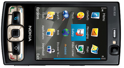
The Nokia N95 8Gb handset

Whilst on one of my ebay fishing expeditions I noticed that the N95 8Gb display was widely available and very cheap at about £4.50 for a clone panel from one of the multitude of HK-based sellers.

Furthermore, it shared the same JST connector as my previous reverse-engineering efforts and a little googling yielded the repair manuals that contained the schematic.


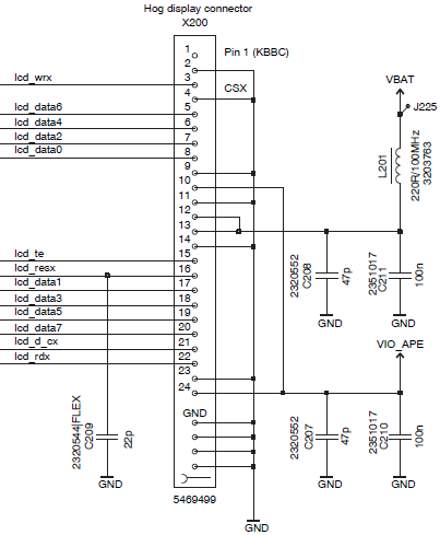
The phone connector schematic from RM320/321

Pretty quickly it became obvious that this was not an identical pinout to the 6300/N82. For a start, where’s the LED backlight in and out connection? It’s just not there. The other pins are familiar though, so I’ll get started and see if I can work out the differences as I go along.

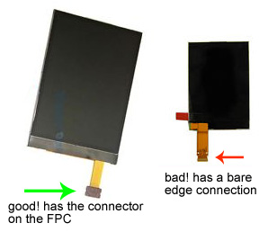
Note that the N95 and the N95 8Gb are different phones with different LCD connectors. The N95 has a flat FPC connection that I have not yet been able to identify. The 8Gb model has the familiar JST 24R-JANK-GSAN-TF 24-pin board-to-board connector.


The two N95 variants as shown in ebay ads

Here’s a close-up of the connector fitted to the screen that I bought. The manufacturer has helpfully labelled the pin numbers on the FPC. In this case the numbering is correct but it’s never safe to rely on that and you should always find the correct pin numbering by locating the GND pins that connect directly into the FPC ground pour.


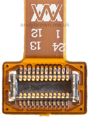
A close up of the JST connector

At 2.8 inches across the diagonal the N95 8Gb is the largest of the three sizes that I’ve reverse-engineered so far. The N82 was 2.4 inches and the 6300 the smallest at only 2.0 inches.


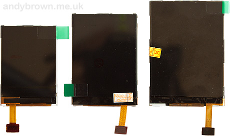
The 6300, N82 and N95 8Gb screens

All of the screens share the same 320×240 QVGA resolution. The pixel size and density are the variables that change along with the physical dimensions of the panel.

Reverse engineering

To get started I hooked it up to an STM32 development board as-per the schematic and tried it using the MC2PA8201 driver that I developed for the Nokia 6300 and N82.

It didn’t work.

It wasn’t a total failure though. I did notice some interesting behaviour.

  • When power was applied, and before RESET was asserted, the backlight came on for the briefest of instants. This could only mean that the backlight LED driving circuit is internal to the panel. This is good news as it will save me a number of components on a development board.
  • A panel with no backlight is so dark that it looks like it is off. By shining a bright light at the panel I could see that it was on and displaying some graphics although they were garbled and not showing correctly. More good news, the post-reset initialisation sequence must be more or less correct.

The next step was to run my test program that issues each of the possible 255 register-write operations and then reads some values back in the hope that the register I just wrote was a command to the panel to give me back some information.

Most of the commands gave only zeros but some of them yielded values. Here’s what I got.

04 : 29 29 91 5B 29 29 91 5B 29 29 
09 : 06 06 61 00 00 06 06 61 00 00 
0A : 08 08 08 08 08 08 08 08 08 08 
0B : 0C 0C 0C 0C 0C 0C 0C 0C 0C 0C 
0C : 66 66 66 66 66 66 66 66 66 66 
0F : F0 F0 F0 F0 F0 F0 F0 F0 F0 F0 
20 : 20 20 20 20 20 20 20 20 20 20 
2E : 00 A0 0C A0 A0 58 48 B0 80 40 
D0 : 40 40 01 40 40 01 40 40 01 40 
D1 : 41 41 01 41 41 01 41 41 01 41 
D2 : 40 40 01 40 40 01 40 40 01 40 
D3 : 41 41 01 41 41 41 01 41 41 41 
DA : 29 29 29 29 29 29 29 29 29 29 
DB : 91 91 91 91 91 91 91 91 91 91 
DC : 5B 5B 5B 5B 5B 5B 5B 5B 5B 5B 
DD : 00 29 91 5B 29 29 91 5B 29 29 
FC : 09 09 00 09 09 00 09 09 00 09 

Most of those mean nothing to me, but registers 0x04 and 0xDA to 0xDD are interesting. They match the behaviour of the device code readout from the MC2PA8201 used in the Nokia 6300 and N82.

Now I know that I’m looking for a controller that has a similar register set to the MC2PA8201 but has additional support for a firmware controlled backlight.

It’s an LDS285

I found a few controllers from Ilitek and one from Himax that supported firmware backlight control. None of their registers worked. Finally I tried the LDS285. This one worked. I was able to switch on the backlight and control its brightness via the registers.

I have no way of telling whether the controller is a genuine LDS285 or whether it’s a similar one that has a compatible command set, but I do know that enough of the commands work for me to be able to create a complete software driver.

You can download the 2.8Mb LDS285 datasheet as a PDF file from here.


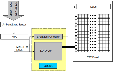
The LDS285 brightness block diagram

Now I knew the identity of the compatible controller it was a simple matter to create a driver to support the LDS285. All features are working and I’m pleased to report that the screen I got from ebay supports 16M, 262K and 64K colour modes. The 64K mode only requires 2 transfers per pixel and so it is up to 33% faster than the 18 and 24-bit modes.

An Arduino development board

Designing a development board for the Arduino Mega would complete the family of three so I decided to do it. I will be using the XMEM interface just like in my 6300 and N82 boards.

The same NXP 74ALVC164245 level converter will be used to convert between the 5V arduino signal levels and the 3.3V signals required by the panel. There are many ways to convert levels and I prefer the NXP IC because it has a very fast 2.9ns propagation time that is guaranteed equal across all 16 of its ports, something that’s very important when you’re dealing with a data bus.


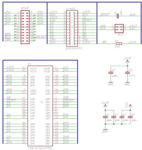
The Eagle schematic, click for a PDF

The schematic is simplified by the elimination of the NCP5007 backlight driver circuit that we used in the 6300 and N82 designs. I have chosen to enhance the stability a little by including a 22pF decoupling capacitor on the RESET line, just as Nokia have done in their schematic.


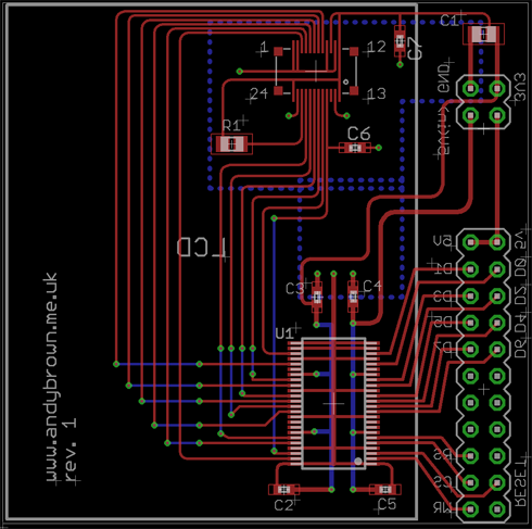
The Eagle CAD design, click for a PDF

The CAD layout was easier than the other boards because the backlight driver circuit and the EN pin header have been eliminated. Working within the 50mm x 50mm constraints means that the panel will be longer than the board by about 20mm on the long side.

Bill of materials

Here’s a complete list of parts used in this project.

Identifier Type Value Footprint
C1 Ceramic capacitor 4.7µF 0805
C2,C3,C4,C5,C7 Ceramic capacitor 100nF 0603
C6 Ceramic capacitor 22pF 0603
R1 Resistor approx 33KΩ 0805
U1 Level converter 74ALVC164245DGG TSSOP-48
MEGA Pin header 2×11 2.54mm
SV2 Pin header 2×2 2.54mm
NOKIA12x2 B2B connector 24R-JANK-GSAN-TF 0.4mm x 24

Building the PCB

Once the CAD designs were completed I exported the Gerber CAM files and sent them off to ITead Studio for production.

Three weeks pass by…

Ordering prototypes from China is great value but you do need to have patience! I used the time to write the Arduino LDS285 driver software that I’d need to use to test the new design. In fact I had so much time I also ported the driver software across to stm32plus in preparation for the next release of that library.

Finally they arrived and I’m happy to say that they appear to be flawless.


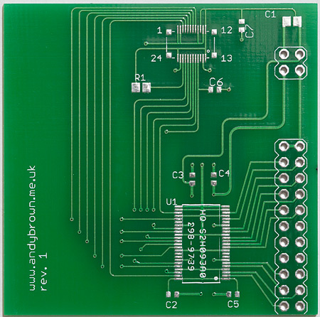
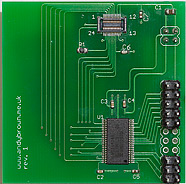
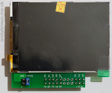
The front of the PCB

There’s more space on the component-side of the board because we don’t need the LED backlight driving circuit that we have on the N82 and 6300 boards.


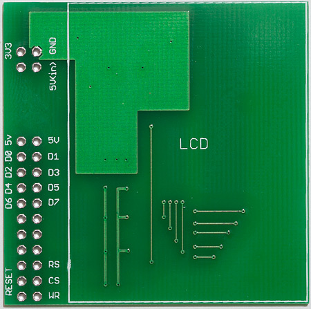
The back of the PCB, which will actually be the front when the LCD is mounted on it

Assembling the components on to the board is a procedure that I’m now well-practised at.

Firstly the two fine-pitch components, the 0.5mm pitch level converter and the 0.4mm pitch socket, are reflowed into place using a hot-plate and touched up afterwards under a binocular microscope.

Secondly the remaining passive components, the capacitors and the resistor, are mounted using my Aoyue 852A hot-air gun. The final step is to hand-solder the pin headers into position with a normal soldering iron.

When it’s all done I wash the boards with soapy water and a toothbrush to remove the flux residues and then I leave them to dry in the airing cupboard overnight.


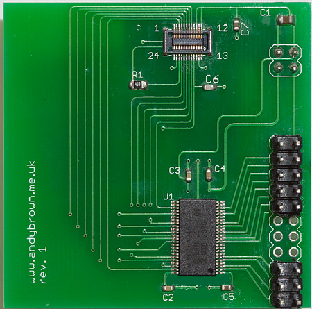
All built and ready to accept a screen

The next day when the board had dried out I attached the LCD. My measurements of where the socket would need to be positioned on the PCB were correct and the LCD sat just where I had envisioned it.


The screen is somewhat larger than the PCB

The screen is fixed to the PCB with an array of double-sided sticky pads that serve both to lift the metal back away from the PCB as well as to hold it fast to the board. Still, the significant overhang necessitates careful handling to ensure that the board is inserted and removed while gripping the PCB edges and not the screen.

Fire it up and run the demos

The software suite that I wrote for the N82 and 6300 is designed to be modular and so it was a trivial matter to write a driver for the LDS285 that would necessitate only a one-line change in the example programs to work with this new display. You will require at least version 2.3.0 of the driver.


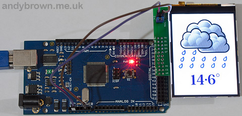
Raining again? It must be summer in England.

To use the new driver we simply replace the include file that makes the driver definitions available to us:

//#include "Nokia6300.h"
#include "NokiaN95_8Gb.h"

And we change the typedef that gives us access to the panel driver:

//typedef Nokia6300_Landscape_262K TftPanel;
typedef NokiaN95_8Gb_Landscape_262K TftPanel;

I’m happy to say that all the driver functionality is available and the panels that I’ve tested so far all support 64K, 262K and 16M colour modes in landscape and portrait orientations.

Watch the videos

I’ve put together a quick YouTube video that shows the graphics library in action on the N95 8Gb. That should give you a sense of the size of this panel relative to the other ones I’ve reverse engineered.

This first video shows the panel attached to a 128K Arduino Mega:


This second video shows the panel attached to an STM32F4 Discovery board using the LDS285 driver found in my stm32plus library. When attached to the 3.3V STM32F4 device the level converter IC is just a pass-through with 3.3V on each side.


So that’s it, another Nokia QVGA panel gives up its secrets to the hobby engineering community. I hope that the information I’ve published here will be of some use to you and your projects.

Update: 1st December 2012

I’m not at all surprised to announce that, just like with the Nokia 6300 display, there is more than one variant of the display out there. This second variant that I’ve seen flips the column and row ‘cursor’ position commands in portrait mode. Other than that, it’s just the same.

I’ll be calling this variant ‘Type B’ and it will be supported in version 2.3.1 of my Arduino drivers that I hope to release tomorrow, the 2nd of December. Usage is just the same pattern as the 6300, all that is required is the suffix _TypeB on the driver name. e.g:

typedef NokiaN95_8Gb_Portrait_262K_TypeB TftPanel;

TftPanel *tft;
tft=new TftPanel;

Schematics, CAD and gerbers available

I have open-sourced my PCB design and CAD files so if you’re interested in building your own boards then head on over to my downloads page and grab yourself a copy.

Some boards for sale

I’ve constructed the remaining PCBs that I have and am selling them on a first come first served basis. The price including delivery is £16.90 for UK and £18.49 for anywhere else in the world. They come with the LCD fitted and are ready to plug in and play.

Temporarily out of stock! I’m building a new batch and expect to be completed on December 15th, 2012. Please check back here later.


Location


  • Frank

    Another great write up!

  • Jahn

    Excellent job!
    How much time did you have to spend on this reverse engineering? Reverse engineering is very interesting hobby for me also but time consuming 🙁

    • Countless hours on the initial 2730 reverse engineering then the others after that are all based on the same principal. Like you I find it very interesting and challenging. It's a great feeling when you succeed too!

  • mahendra

    hey,,,,Andy Brown,,
    thanks ….
    it is really really good…
    excellent work…

  • sethu

    Good attempt,
    Could you share the voltage rage of VBAT and VIO_APE?

    • Yes of course, please refer to section 8.6 "DC characteristics" of the LDS 285 datasheet.

      • Froggy

        Hi Andy, your work is very useful ! 🙂

        I noticed that on the Nokia schematic, pins 12 and 13 are both connected to VBAT, but on your schematic, pin 13 is connected to GND ?
        So I wonder what is that pin 13 doing since it seems it can be connected to +3.3V and GND and work the same ?

        Thanks !

        • Hi, please note that the pin numbers on my connector are not ordered the same as on the Nokia schematic. Confusing I know but I created that connector footprint with its numbering for the first phone that I reverse engineered (2730) and re-used it for every subsequent phone with the same connector so a translation has to be applied from Nokia's numbering to my connector!

          So for the N95 8Gb, Nokia #1 = 13, Nokia #12 = 24, Nokia #13 = 1, Nokia #24 = 12

  • Blackchicken Cz

    Hi Andy, first of all, I was very impressed when I saw your videos on youtube. I love it. Im really new in Arduino and programing at all. Im currently building my first project, reef aquarium cotroller with two temp sensors and 4 led dimmable circuits, maybe Ph and ORP for my 400l glass baby hehe. LCD 4×20. But still a lot of work and learning. Your inspire me a lot, and next project will be definitely large LCD TFT TOUCH SCREEN reef controller, hope one day.

    I have one question, I`m very confused with creating simple menu. May I programe it by my self or use some library like MENWIZ. Just want to keep things simple and understable for beginning.

    So keep working and a lot of good in new year.

    • Hi there. Thank you for your comments. The menwiz library won't work with this LCD as it's designed to interface with the character LCD library for the Arduino. You would need to program it yourself. The graphics library that I supply has all the required drawing primitives that you would need and you would write your menu logic using those calls. Note that these Nokia cellphone LCDs do not come with a touch screen attached.

      Regards,
      – Andy

      • Blackchicken Cz

        Hi Andy, Thanks for repply. Sorry for confusing my question. Im creating some menu for libraries for standart LCD HD44780 interface, and Im really confused what to use. Do you have some tip for beginners how to jump into menus? And yes I know that N95 LCD is not touch but on the market is some Touch compatabile with Arduino. So If I want some nice graphical menu I can use some nice jpg pictures together with text, right? Something like in Flash? Im asking because with simple rounded squares, circles will be difficult to do something really nice and say profi. But as I can see on youtube, loading jpg pictures is relatively slow, or it is possible at this moment with your library to refresh display say fast as my SG note? (-: Sorry for my question just Im interest in this thing. Thanks a lot

  • almightytech

    hey,,,,Andy Brown,,
    your reverse eng. is very very useful.
    thanks..

  • Ben

    Excellent work, I’d like to try with my arduino and n95. How can I order the circuit card.. Thx

    • Hi Ben. I'm all sold out at the moment. I'll post back here if I decide to build another batch.

      – Andy

      • Ben

        Thx andy any chance on the Eagle CAD file for this board then?

        • There certainly is. I've updated the post with a link to the downloads page where you can get the schematics, CAD, gerbers etc.

  • Henrique

    Firstly, I found his work excellent, very good! Congratulations!
    I'm interested in using this display and your library, but with the Arduino Due, this is possible? What should I change?
    Taking into consideration that the DUE already has output at 3.3V, so i will not need to use the logical drive, right?
    Excuse me the many questions, I'm new in this regard, but I'm eager to learn. I would appreciate if you could help me.
    Thank you very much!

    • Hi Henrique,

      Thank you for your comment. You can definitely hook this up to the Due. I have no direct experience with it but it's an ARM and it supports an external memory interface and that's all good news. You could potentially start with my Arduino Mega driver and create your own access mode class to handle the communication with the display.

  • C User

    Hey congratulation for this great work. Did somebody convert the Code from C++ to C? I want to use it on STM32F4 Discovery in a C toolchain but at the moment its hard for me to find a way to write it in C. Is there some material from the reverse engineering where i could see the timing etc.?

    • Hi,

      Not seen a C++ to C port out there yet. Most of these 8080 LCDs are similar enough that you can start with a skeleton implementation for a different controller that's coded in a way that fits your toolchain and hardware pinout, strip out the initialisation sequence and plug in the initialisation sequence and any other commands with those from my code. The FSMC timing is right up front in the demo code (look at lds285.cpp). I use address/data setup timings of 0/2 hclk's.

      – Andy

  • Atar

    Hi Andy, many thanks to you, i am successfully driving N95 8GB with your library on Arduino. i used the same 74ALVC164245 level converter and it's work like a charm.
    what i have to do next is driving the LCD with my STM32F4Discovery board because i believe it will be faster than arduino. i built your stm32plus with scons and programmed my discovery board with pre-compiled lds285.hex located in "…/usr/lib/stm32plus/2.3.0/example/lds285".
    when attached to my discovery board, pass through the level converter, the LCD was garbled and not displaying the graphic correctly. i've checked the connection and tried compiled multiple combinations of mode in scons but i've failed so far.
    any ideas?
    Thanks.

  • Hey Andy Nice hack! I was having trouble sourcing the connector
    i tried ordering from JST webshop the order went through but then they emailed me saying that they cant sell it to me 🙁
    digikey has the connector but the MOQ is 4k! :O 🙁
    any other alternative to the connector ? or any other place where i can get it from for a reasonable price?

    • Hi, try "www.cellnetos.com". Search for "2730 LCD" and it will be the only result at $0.81 per unit. They will ship EMS at reasonable cost.

  • Great write up Andy! Detail is great!

  • Jafari

    hi andy.
    thank for your very useful technical information about mobile tft LCD.
    i use stm32f103ret6 with a Chinese lcd known as "N96 mobile lcd" that has ili9320 controller.
    im going to test N95 8GB LCD and googled it…
    as u know there isn't such precise information in this field…
    some where mentioned that the n95 8GB controller is S6D0154X and some saied s6D1130X01 !
    as i use EMWIN sagger graphical library in my projects, supporting the controller by emwin is very important to me,so non of s6D1130X01 and S6D0154X and LDS285 is supported.
    is it possible that the LDS285 and s6d driver series is similar?
    have you any idea or experience about emwin supported drivers?
    finally do u know what is the driver chip of the Sony Ericsson Vivaz lcd?(its a 3.2" high quality and cheap lcd:-D )

    • Hi Jafari,

      I have no experience with emwin. It would be nice if there was an open source version of that library then we could add our own drivers. Thanks for the tip on the Vivaz, I will definitely do some investigation on that one.

  • Jafari

    is it possible that the LDS285 and s6d driver series has similar codes or functionality?
    are you definitely sure that the n95 8GB driver is LDS285?

    i have a question:
    where integrated the driver chip in the physical case of LCD or cable?i parted a LCD and i didn't find any IC in it,only had some resistor and cap…!!!??

    i use KEIL uvision toolchain that has emwin sources itself.(ver 4.5 or above)
    *Keil4.7ARMSeggeremWin
    u can use it for test…

    • It is possible that two drivers have compatible registers. The datasheets for the LDS285 and your Samsung driver are both available online for you to make your own comparison. I am sure that the N95 8Gb is either an original LDS285 or one that is 100% compatible otherwise my design simply would not work. The software backlight driver is one of the key identifying factors – very few drivers do this.

      The driver is COG. See: http://www.nxp.com/documents/white_paper/LCD_Whit

      I'm not interested in supporting any closed source software.

  • Jafari

    yeah body
    thank for your nice pdf. very useful for me…
    i bye a N95 8GB about $4.5 and a vivaz u5 LCD about $10 that i interested in them, i'm working on them.
    some where we have to use closed source software, but definitely every one's first choice is open source.

  • jafari

    hi dear andy
    i have some questions:
    1- witch interface u used? 8080 or 6800 parallel interface?
    2- what is the initializing values that u used for init the lds285 registers?i cant find them in your code.
    great thanks.

  • Umut

    Thank you Andy, you inspire me a lot. I just started working with TFT LCDs.

  • Daniel H

    It looks like the connector-free version of the display uses an odd 23-contact offset pinout. The repair manual pictures a tool for opening the 'JAE' connector. Maybe it is the FB8S023JA1 which is available on digikey.

    • Do you mean the N95 (non 8Gb) phone? I believe that one has the FPC tail with staggered contacts on it. It would be nice to know for sure if someone can confirm that's the compatible receptacle.

  • Dear Andy,

    Please produce N95 carrier PCB board. I want to buy it like many others.

    thanks

  • Muhammad Saad

    excellent post.keep it up.I just bought a nokia n95 8gb lcd and connector for $3.5 .They are cheap here in our area.I will be working on it soon.Plus i will also add a resistive touch screen to it.

  • Anil Kumar

    Good Work. Very helpful.
    LDS285 data sheet section 8.6 says max VDD1 when PSEL=0 is 1.95V. section 4 says a capacitor needs to be connected to VDD1 when PSEL=VDD2. The LCD may have one of the pin as PSEL which currently connected to ground.

  • Anil Kumar

    Good Work.

    may be one of the pin presently connected to ground is PSEL. is there any idea to find the pin.

  • JHOAN SEBASTIAN MARIN VELASQUE

    hey andy great job …
    I have a question, as you can adapt this to arduino DUE n95 lcd ??
    Some months ago achieves make a very rough version of your lcd n95 but this does not have the level converter 74ALVC164245DGG your use
    thank you very much hope your answer

    • Hi there. I believe the Due is a 3.3V board so you don’t need a level converter.

      • JHOAN SEBASTIAN MARIN VELASQUE

        hello andy …
        andy clear that’s why I would like to connect this lcd to arduino DUE because it works with 3.3 volts besides that has a very fast clock. the problem is in terms of libraries, I’m a beginner and nose como organize DUE arduino pins to operate the lcd n95 a little help please

        thank you very much

  • ibrahim

    Hi, Andy
    VIO_APE seems like 1.8V on nokia schematic.
    You had connected VIO_APE to 3.3V. Did you encounter any problems about this?

    In LDS285 datasheet;
    Optional logic supply voltage range
    VDD1 to VSS1 (when PSEL=Low): 1.65 to 1.95V
    VDD1 to VSS1 (when PSEL=High): 1.95 to VDD2
    VDD2 range 2.3V to 3.3V

    One of the pin which connected to GND in nokia schematic (and yours) can be “PSEL” pin.
    If it so, that pin must be connected to VBAT for connecting VIO_APE to 3.3V.
    Do you have any idea about this?

  • Saman Hosseini

    Hi Mr Brown!!!

    I want to use your best Project and so thanks for the develop and create !!!

    I have a question and It is that can I change pins your library for example change place’s pin RS(37) to 33 and or CS(39) to 34 and or WR(41) to 35 and Reset(35) to 36!!!? Is that possible to change !!!? thank you very much and HAPPY CRISMAS and new year…

    • It is possible to move those pins if you drive the LCD using GPIO. You can see example pinouts for the 16-bit GPIO mode here and the 8-bit mode (requires a latch) here. The GPIO modes require a full port for each data word. e.g. Atmega pins PA0..PA7 == LCD data lines D0..D7.

      If you want to use the XMEM mode then you cannot move the pins because they correspond to fixed locations in the XMEM peripheral on the Atmega.

  • digi thomas

    I’d like to recreate the same thing. However i’m having some confusion with the pcb prototyping website. There are a lot of diffrent options. Do i just take the cheapest max 5×5 cm? Arn’t there any unexpected costs and what does the open source option mean?

    • Hi, the cheapest 5x5cm will work. This is a cheap option and all the defaults on the web form are correct and do not need to be changed:

      http://www.elecrow.com/5pcs-2-layer-pcb-p-1174.html

      Or you can change the “PCB Color” if you want to personalize it a bit. Most of the colors are free.

      • digi thomas

        Thank you a lot. I appreciate you taking your time for me.

  • Doni Mart Galumbang Hutabarat

    Hi andy. i have rear camera nokia of 5800 xpressmusic and galaxy note 3 rear camera. would you like helping me interfacing those camera using I2c. i want those camera as external camera of OTG-enabled samsung smartphone via USB. thank you

  • mahdi zamani

    hi
    its good job but i cant answer frome it!!!
    can place a hex file for stm32f4 discovery board for test the hardware ?
    thanks
    mahdi

  • Unfortunately I have the flat connector type display, I was looking for information to make it work on my Raspberry Pi 3.

    Do you have any idea where I can find information to connect salvaged displays to a Raspberry Pi 3 and how to get the drivers installed for a custom display?

    I also have a TomTom Go 1005 that uses a Samsung LCD and I’ve found all the necessary info to make use of the Atmel chip to be able to communicate with the display and even use the touch screen when I connect it the right way, however I can’t use the connector which is exactly the same as you describe here that you needed the Nokia display to have, I just have to solder the signal wires directly to the flexible pcb on the backside and that’s no problem either because all hackable points are conveniently shown with a gold pad and a label so that couldn’t be made any simpler than that.

    I’m just not really sure and I don’t want to destroy my Raspberry Pi 3 or the 7″ touchscreen so it would be helpful if you could help me a little bit with the connections and the rest I’ll be able to figure that out on my own.

  • Hossein

    “As I resolve issues and fix problems I will write them up here in the hope that you can make use of them yourself. Any said”
    You really do it.
    ممنونم