


Building the phototrap. Part 5: The long range infra-red beam sensor
All the phototraps that I’ve seen on the internet include some variation on the infra-red beam breaking sensor. The technique is simple to explain. You place an infra-red source directly in-line with an infra-red emitter and when an object comes between the two you trigger the camera, or a flash. Job done. Well, in theory at least. Here’s an account of the fun that I had.
The naive design
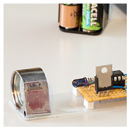
Initially while playing around I hooked up an IR LED, in this case an Osram SFH484 that has a nice tight half-angle and a 100mA max sustained current. I fitted the appropriate series resistor and on another board I hooked up a photodiode who’s datasheet indicated that it gave the strongest response in the same area of the spectrum as the IR LED. Confidence was running high at this point.
Sadly my expectations were quickly brought back down to earth when I realised that I could only get a few centimetres range in total darkness. Turn the lights on and it barely worked at all. There were two main problems that I quickly identified.
Firstly, 100mA isn’t nearly enough to get decent range. I was going to have to seriously crank up the juice if this was going to be a practical proposition.
Secondly, and most importantly, infra-red radiation is emitted by anything and everything that gives off light or heat and these ‘noise’ sources quickly drown out your ‘signal’.
Max power
A few hours of internet research and much studying of datasheets later and I discovered the solution to the power problem. Instead of running the LED on a continuous current you can get much MUCH higher output if you send short pulses of current to the LED interspersed by gaps designed to be of sufficient size to allow the device to cool before it burns itself out. Do this fast enough and the LED will appear to the human eye to be continuously on and very bright indeed.
The device I chose was the Vishay TSAL6200. The reason for this choice is because it pairs well with a Vishay sensor that we’ll come to later on, and also because it can be pulsed up to 1000mA given the right pulse design. Mouser has these for about 30 pence each.
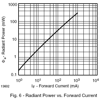
The power versus current chart
The sensor
The answer to the interference problem is pulse modulation. What this means is that instead of emitting a continuous HIGH signal during your pulse on state, you modulate on and off at a known frequency. 38Khz appears to have been chosen as the industry standard for this purpose. You then use a device that will not respond to infra-red radiation unless it is being modulated at 38Khz.
Vishay produce a device that does exactly that, it’s the TSOP4038 and it couldn’t be simpler to use. There are only 3 pins: power, ground and output. When a 38Khz signal is received the output pin goes high and when there’s no signal it stays low.
Studying the datasheet shows that Vishay’s own test conditions for the TSOP4038 used a TSAL6200 emitter pulsed at 600mA with pulse widths and gaps of 600 microseconds.
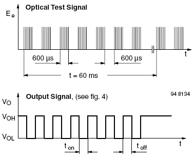
The pulse characteristics and sensor response
I had an email exchange with a very helpful gentleman in tech support at Vishay who confirmed that such an arrangement should be good for 5 metres or so of range without any external optics and that the TSAL6200 made a good pair with the TSOP4038.
So that was that, I now had a specification. I was going to build a TSAL6200/TSOP4038 combination pulsing the LED at 600mA with a pulse size of 600 microseconds. The range quoted to me of 5 metres sounded like enough for the purposes of a phototrap but I wondered if I could beef that up a little with some custom modifications…
Emitter design
In my phototrap the sensors are wired to the control box and the emitters, if required, must be standalone. Therefore my design is a self-contained battery powered unit. The clever stuff to do the pulse timing and modulation is handled by an ATtiny85, a very cost-effective MCU from Atmel that comes with 8K flash and 512 bytes of SRAM. Not a lot, but more than enough for this application and the MCU costs less than £3.
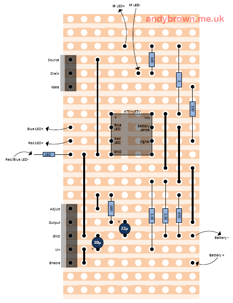
Here’s the circuit diagram.
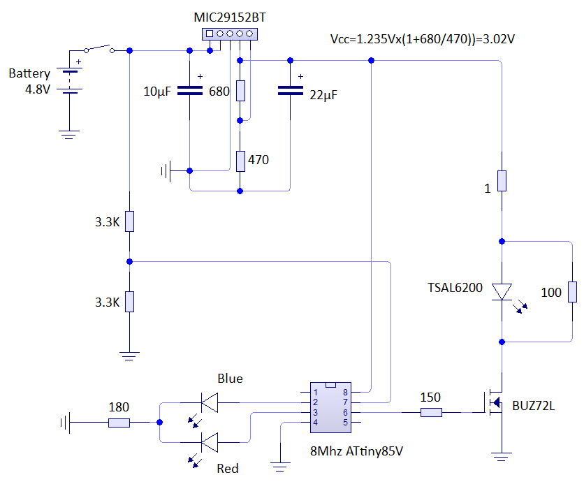
Click for larger
The device is powered by four AA rechargeable batteries, giving an input to the adjustable voltage regulator (the MIC29152BT) of 4.8V. The 680Ω and 470Ω resistors are used to program the MIC29152 to output 3.02V, about as near to my target of 3V as possible using standard value resistors. The goal was for a full charge to last at least 6 hours of continuous use – something I easily achieved.
The TSAL6200 datasheet shows that the forward voltage of the LED at 600mA is around 2.2V. That suggests I need a series resistor of 1.2Ω. I didn’t have any of those around so I decided to push the envelope a bit and use a 1Ω resistor which should yield close to 800mA. I’m confident that the LED will handle it because the modulation of the pulses means I’m only going to be driving the LED for a 25% duty cycle. In any case, I bought a few TSAL6200 just in case of burnouts during development!
The two 3.3K resistors form a voltage divider that I use to measure the voltage coming out of the battery. When it’s above 3.8V I periodically pulse the blue LED. When it’s between 3.8V and 3.3V I pulse the red LED. If it falls below 3.3V then the battery power is getting too low and the circuit is in danger of malfunctioning. If such a malfunction were to result in the ATtiny program emitting a constant HIGH level on pin 6 instead of the programmed pulse then the TSAL6200 would quickly burn out, therefore I shut down the program if the battery voltage falls below 3.3V. I can get away with a single current limiting resistor for both the power LEDs because the firmware ensures that only one is ever on at a time.
The modulating pulse is output from pin 6 of the ATtiny85 via a current limiting resistor to the gate of a BUZ72L power MOSFET. This device was chosen because its characteristics were a good match for the voltage used in this circuit.
The 100Ω resistor across the TSAL6200 is a shunt resistor. Without it the voltage in the circuit cannot fall fast enough to maintain a good waveform. Here is a picture of the waveform without the shunt resistor.
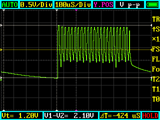
A poorly shaped waveform
As you can see the voltage does not fall to zero in the 38Khz LOW periods and only falls slowly away in the longer pulse OFF period.
Here is the same circuit with the addition of the shunt resistor.
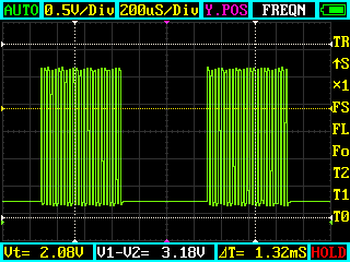
A good shaped waveform
The resolution is different because I wanted to show some complete pulses but you can easily see how much more of a clean shape we’ve got, in fact it’s pretty much ideal.
Emitter firmware
As mentioned earlier the emitter firmware is embedded in an ATtiny85 with 8K of flash memory and 512 bytes of SRAM. This seemingly paltry amount of memory is more than enough because the entire C++ firmware compiles down to only 2878 bytes of machine code.
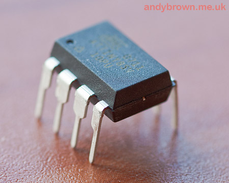
Eight pins are all you need – an ATtiny85
Out of the box the ATtiny85 is set to run at 1Mhz. Unfortunately that is too slow for it to generate the pulses I need and execute the additional functions in the gaps between the pulse changes so I reprogrammed the fuses to 8Mhz and that worked just fine. You can find an online calculator that will generate fuse values for you by clicking here.
I use a port of the Arduino library, basically to get access to the millis() and micros() timing functions. I don’t use any of the other facilities of the library and I’ve moved the timer that millis() and micros() uses from Timer0 to Timer1 so that I can get access to all the PWM wave generation features on Timer0. The ported library is included in the emitter firmware download in the ArduinoCore subdirectory.
One point to note is that the pin numbers used for digitalRead() and digitalWrite do not map to the same as the package pin numbers. Here is the mapping:
// ATMEL ATTINY45 / ARDUINO
//
//                  +-/-+
// Ain0 (D 5) PB5  1|    |8  Vcc
// Ain3 (D 3) PB3  2|    |7  PB2 (D 2) Ain1
// Ain2 (D 4) PB4  3|    |6  PB1 (D 1) pwm1
//      	    GND  4|    |5  PB0 (D 0) pwm0
//                  +----+
Setting up the 38Khz PWM output
The following code is used to program Timer0 to generate a 38Khz signal on pin 6.
void IREmitter::create38KHz()
{
// switch off

	pinMode(1,OUTPUT);
	digitalWrite(1,LOW);

// COM0A = 00: disconnect OC0A
// COM0B = 00: disconnect OC0B; to send signal set
//              to 10: OC0B non-inverted
// WGM2 = 101: phase-correct PWM with OCRA as top
// CS2 = 000: no prescaling

	TCCR0A=_BV(WGM00);
  TCCR0B=_BV(WGM02) | _BV(CS00);

// the top value for the timer
// the modulation frequency will be SYSCLOCK / 2 / OCR0A

  OCR0A=F_CPU/2/38/1000;
  OCR0B=OCR0A/2; 								// 50% duty cycle
}
The above calculations owe much to the work done by Ken Shirriff in his IR remote library. It would have taken me much longer to decipher the timer registers without his good work.
The main loop of the code basically looks like this
	for(;;)
	{
	// high

		TCCR0A|=_BV(COM0B1); 			// Enable pin 6 PWM output

	// check the power level

		then=micros();
		voltage=_powerCheck.checkPower();
		now=micros();

	// delay for the remaining time

		delayMicroseconds(PulseLengthMicros-(now-then));

	// low

	  TCCR0A&=~(_BV(COM0B1)); 	// Disable pin 6 PWM output

	  if(_powerCheck.getConsecutiveCriticalSeconds()
          >CriticalPowerShutdownSeconds)
	  	shutdown();

	 // output power level indicator to appropriate LED

	  then=micros();

	  if(voltage<PowerCheck::LowVoltageThreshold)
	  {
	  // if we are switching from power ok then ensure that
    // the ok led is off

	  	if(!_lowPower)
	  	{
	  		_powerOKPulser.stop();
	  		_lowPower=true;
	  	}

	  // pulse the low power led

	  	_powerLowPulser.pulse();
	  }
	  else
	  {
	  // if we are switching from low power then ensure that
    // the low power led is off

	  	if(_lowPower)
	  	{
	  		_powerLowPulser.stop();
	  		_lowPower=false;
	  	}

	  // pulse the OK led

	  	_powerOKPulser.pulse();
	  }

	 // get the time now

	  now=micros();

	 // delay for the remaining time

	  if(now-then<PulseLengthMicros)
	  	delayMicroseconds(PulseLengthMicros-(now-then));
	}
The logic in the infinite loop goes like this:
- Switch on the wave output
- Take a measurement of the voltage from the potential divider
- Do nothing for the remainder of the 600 microsecond pulse
- Switch off the wave output
- Shutdown if the power has been below a critical level for a predefined length of time
- Start or continue pulsing the red led if the power is low, or blue if OK.
- Delay for any remaining time in the pulse length.
- Go to step 1
With so few pins on the ATtiny I don’t have the luxury of a spare timer that I can use to generate a real PWM waveform just for the purposes of producing the nice ‘heartbeat’ LED fade in/out effect. To get around this I wrote an asynchronous LED heartbeat class that just needs me to call pulse() regularly while I want the effect to continue and stop() when I want it to switch off quickly.
Emitter Build
I decided to build the circuit on cheaply available stripboard rather than go to the extra effort and expense of having a PCB built. The stripboard layout is shown below. The two empty rows at the top and bottom are by design so I have some space to mount rubber feet in the corners.
Click to download a PDF
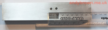
I mentioned earlier that I was going to power the emitter from a set of four AA batteries. With this in mind I decided to mount the circuit and batteries inside a 40mm square box section aluminium tube that I got on ebay for a few pounds, complete with a pair of very handy push-on end caps that could be modified to hold connectors and drilled to let out the IR beam.
The emitter enclosure drilled to accept the on/off switch and the two power leds
Assembling the board only takes an hour or so because the components are quite well spaced apart and stripboard is generally quite easy to work with. Here’s the assembled board with the ATtiny85 mounted in an IC socket. I programmed it externally then simply pressed it into place.
The MIC29152BT voltage regulator was a bit of a pain. Although it came in a standard TO-220 package it crammed five pins into a space where you would normally get three meaning that I had to do quite a lot of gratuitous outward bending with some needle-nose pliers to slot the pins comfortably into the 0.1″ stripboard grid.
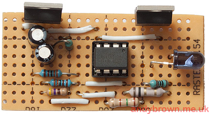
The assembled board
Using optics to extend the range
I knew from my conversations with the Vishay engineer that I was going to be good for the planned five meter range but I got to thinking, why not try to get more? So let’s see what we can do with some external optics.
Unsurprisingly the answer came on ebay where I picked up one of these magnifying loupes from a seller in China for a few pounds.
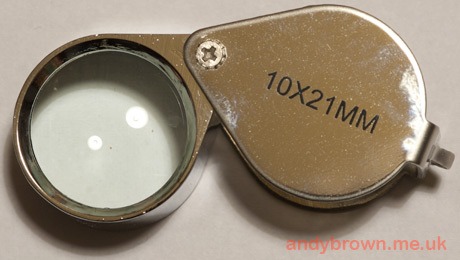
Cheapo loupe
The optical quality of the loupe is terrible! No attempt seems to be made to correct for field curvature so you can have the center in focus, or the edges but not both at the same time. Nice! Anyway, none of this is in the slightest bit important for our purposes. We just need it to magnify, and that it does very well.
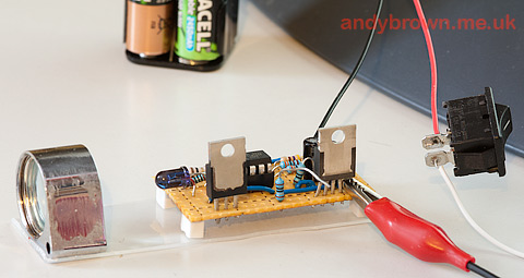
Firstly we unscrew the cover and discard it, then we determine the working distance of the lens from the LED like this:
Calculating the working distance
What I’ve done here is to place the loupe in front of the board, which has a power supply connected. Now I move the loupe backwards and forwards until the point where the image of the LED fills the entire surface of the magnifying glass. Then I stop and measure the distance from the lens to the LED and that’s the working distance.
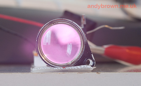
But hang on a second, isn’t this infra-red? How can I see it? The trick is to view the scene through either a camera-phone or any point and shoot camera with an LCD viewfinder on the back, i.e. nearly all of them. These camera’s have sensors that are sensitive to IR and the LED will show up as purple on the LCD.
Don’t be tempted to rig up any old visible LED just to work out this distance. Unless you get the half-angle matched directly with the IR LED then the working distance will be different.
All hooked up
Here’s what it looks like ready to go into the enclosure. The loupe and the board are superglued on to a strip of perspex that I cut from some packaging that was otherwise heading for landfill. The board itself is additionally mounted on four square ‘feet’ cut from an eraser and superglued into place.
Delicate mounting procedure
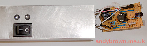
Mounting the board in the case needed a bit of forward planning. Wires had to be attached to the switches and LEDs before threading them out through the end of the case and then soldering them to the board. Before slotting the board back into the case and gluing it to the bottom.
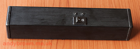
The painted emitter
Here’s the finished item after painting and sealing with a lacquer. The front end-cap has a hole drilled to allow the IR LED to shine through and the rear cap pops off to expose the AA battery pack which slides out for easy access.
Receiver Design
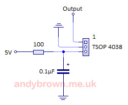
Very simple circuit
Thanks in no small part to the high level of integration offered by the Vishay TSOP4038 we can use the application circuit given by Vishay in the datasheet for the device. Just one resistor and one capacitor are required as external components. I supply 5V and ground from the Arduino and the output goes back to an input pin on the Arduino.
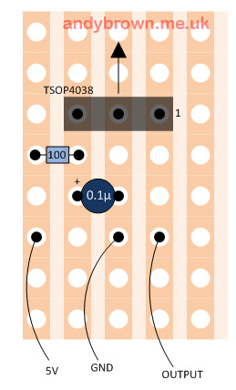
The stripboard layout
The stripboard layout reflects the simplicity of the circuit. As with the emitter I have left a little extra space at the corners to mount the rubber ‘feet’ that I cut from a pencil eraser.
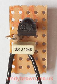
The receiver stripboard build with two of the three leads connected
The receiver software
The receiver software is a little more complex than the simple emitter. I designed it to cater for varying strengths of signals, to be resistant to false positives and to operate in two different modes.
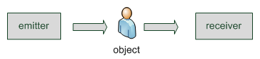
Beam break mode
The first mode is beam-break triggering. In this mode the beam is normally detected by the receiver and is interrupted by an object that passes in front of it. This is the mode that can operate at the longest range. The disadvantage is that for photographic purposes you normally need two beams designed to cross at a point where you are focussed otherwise your camera could trigger when the object is out of focus. This might not matter if you have a large memory card and don’t care about getting false triggers.
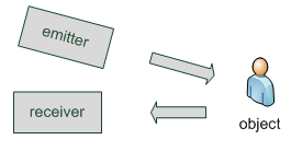
Beam make mode
The second mode is beam-make triggering. In this mode the beam is normally directed off into space and is interrupted by an object passing through it. The infra-red reflectivity of the object causes a trigger because the beam is bounced back into the receiver.
Software design
The basic steps taken by the software are:
- Sample the receiver in as tight a loop as we can, remembering a count of highs and a count of lows
- When a configurable multiple of the beam pulse period (1200µs) has passed, calculate the percentage high’s versus lows that we have received.
- A perfect unbroken beam would be 50% low, 50% high. We say the beam is broken if the calculated percentage falls outside a configurable percentage range.
A snippet from the class definition that declares the receiver is here:
class IRBeamSensorImpl
{

private:
	int _acceptRangeLowPercent;
	int _acceptRangeHighPercent;
	int _samples;
	uint32_t _periodMicros;
	Sensor::BeamTriggerActionType _beamTriggerActionType;

	uint32_t _lastSampleWindowStart;
	uint32_t _sampleWindowMicros;
	uint32_t _counter[2];

public:
	bool hasTriggered();
};
The user configurable variables (lines 5 to 9) are configured using my management user interface, the code for which is not shown here – it’s far too involved and is way beyond the scope of this article. Here’s a few photographs of the the part of the interface that configures these variables:
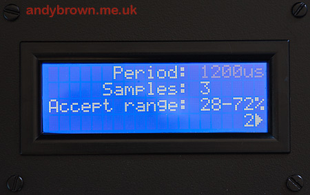
Screen one of the configuration interface
The period looks a bit dull in the photograph because it’s blinking during the exposure!
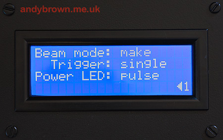
Screen two of the configuration interface
The ‘Trigger: single’ setting is a general configuration option for all my phototrap sensors and is not related directly to this IR sensor. What it does is configure the unit to either fire once when the sensor is activated or continually fire until the sensor is no longer activated.
The state variables are set up thus:
_lastSampleWindowStart=0;
_counter[0]=_counter[1]=0;
_sampleWindowMicros=(uint32_t)_samples*_periodMicros;
The method that manipulates these state variables to determine whether the unit has triggered is shown here. The original code has some extra calculations to convert how far away a percentage is from being triggered and convert that to a ‘signal strength’ meter that is continually displayed by the unit.
bool IRBeamSensorImpl::hasTriggered()
{
	uint32_t now;
	int 		 percent;
	bool		 outOfRange;

	now=micros();

	if(now<_lastSampleWindowStart)
		_lastSampleWindowStart=0;      // must have wrapped, start again

// starting again?

	if(_lastSampleWindowStart==0)
	{
		_counter[0]=_counter[1]=0;
		_lastSampleWindowStart=now;
	}

	if(now-_lastSampleWindowStart<_sampleWindowMicros)
		_counter[!!digitalRead(_receiverPin)]++;		// take a sample
	else
	{
	// calc the percent high

		percent=(int)((_counter[1]*100L)/(_counter[0]+_counter[1]));

	// we're done ready for next time

		_lastSampleWindowStart=0;

	// check if percentage is outside range

		outOfRange=percent<_acceptRangeLowPercent ||
               percent>_acceptRangeHighPercent;

		if(_beamTriggerActionType==Sensor::TriggerBreak)
		{
			if(outOfRange)
				return true;       // triggered
		}
		else
		{
			if(!outOfRange)
				return true;
		}
	}
	return false;
}
Testing

Test results
I tested the range of the emitter/receiver combination outside on a summer’s evening with the setting sun pointing directly at the receiver. I ran out of patio space at 15 metres and at that distance the signal was still full strength. Distances of 20 metres or more should be easily achieved by this design.
Article series index
Use the following links to navigate through this series of articles.
| Part 1: Design | |
| Part 2: The control unit electronics | |
| Part 3: Control unit assembly | |
| Part 4: The operating system | Coming soon! |
| Part 5: The infra-red beam sensor | You are here. |
| Part 6: The X-band radar sensor | Coming soon! |
| Part 7: The PIR infra-red sensor | Coming soon! |
| Part 8: The lightning trigger | Coming soon! |
| Part 9: The ultrasonic trigger | Coming soon! |
| Part 10: The sonic trigger | Coming soon! |
| Part 11: The laser trigger | Coming soon! |