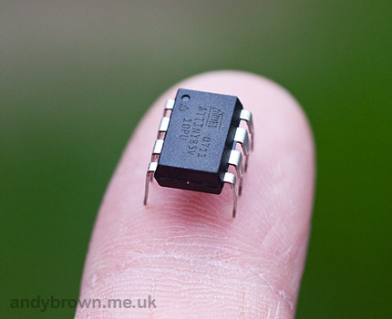
An introduction to the ATtiny85/45/25
The ATtiny range of microcontrollers are ATmel’s smallest and lowest power 8-bit AVR offerings. Typically they come with between 1K and 16K of program memory and 512 bytes of SRAM and 512 bytes of EEPROM.

These MCUs are entirely self-contained. All they need is a stable power supply, and they are remarkably flexible in the voltage range that they can accept. No other external components are required at all. This makes them perfect for small-footprint, low cost devices. In this post I’ll present a summary of the features of the 8-pin ATtiny85/45/25 MCU.
The product range
| MCU | Voltage | Frequency | Flash | SRAM | EEPROM |
|---|---|---|---|---|---|
| ATtiny25 | 2.7-5.5V | 0-20Mhz | 2K | 128 bytes | 128 bytes |
| ATtiny25V | 1.8-5.5V | 0-10Mhz | 2K | 128 bytes | 128 bytes |
| ATtiny45 | 2.7-5.5V | 0-20Mhz | 4K | 256 bytes | 256 bytes |
| ATtiny45V | 1.8-5.5V | 0-10Mhz | 4K | 256 bytes | 256 bytes |
| ATtiny85 | 2.7-5.5V | 0-20Mhz | 8K | 512 bytes | 512 bytes |
| ATtiny85V | 1.8-5.5V | 0-10Mhz | 8K | 512 bytes | 512 bytes |
Speed grading
As you can see from the above table the ‘V’ suffix indicates a model that can run as low as 1.8V at the expense of an upper ceiling of 10Mhz on the clock speed. However, the selected clock frequency does impose a lower limit on the voltage that you can supply.
| MCU | Frequencies | Voltage |
|---|---|---|
| ATtiny25V/45V/85V | 0-4Mhz | 1.8-5.5V |
| ATtiny25V/45V/85V | 0-10Mhz | 2.7-5.5V |
| ATtiny25/45/85 | 0-10Mhz | 2.7-5.5V |
| ATtiny25/45/85 | 0-20Mhz | 4.5-5.5V |
Which one? Where to buy?
System builders will want to choose the smallest, lowest power device that they can get away with and then push down the cost through bulk-buying. Hobbyists like myself will note that all these devices cost roughly the same in small quantities, about £1.30 from Mouser Electronics. Therefore there seems little reason to buy anything other than the 85 or 85V depending on your voltage and frequency requirements.
Pinout

Note the overloading of the function of each pin. This means that you have to be very careful with your design decisions. For example if you want to use analog input 1 then you may not use digital pin 2 because they share pin 7.
Of particular note is pin 1. By default this functions as the RESET pin but you can disable the RESET function using the fuse bits in order to get at the other pin functions. However, if you do that the device will become unprogrammable again except through the use of a high-voltage programmer.
Get the datasheet
Click here to download the datasheet from Atmel. You really can’t do without it.


