


Hacking the HP Z800 Xeon motherboard into a standard case
About four years ago now the company I work for were investing in some new servers for a project that we were working on and what turned up were quad LGA1366 socket Xeons with support for up to 192Gb of memory. In most cases two sockets were populated with Intel Xeon X5670 CPUs, hex core devices with 12Mb of cache memory. We ran Redhat Enterprise Linux on them and they were, and still are, extremely fast linux servers that could operate as physical boxes in our production environment or virtuals in development.
I wanted one. I still want one. I looked around and noticed that HP were doing a very similar board with two sockets and, crucially, it was packaged up into what looked like a normal PC tower case. And it was very expensive, much too expensive to justify forking out for one.
Fast forward four years and times have changed. You can now pick up a brand new replacement motherboard for an HP Z800 on ebay for £100. So that’s what I did, and here it is.
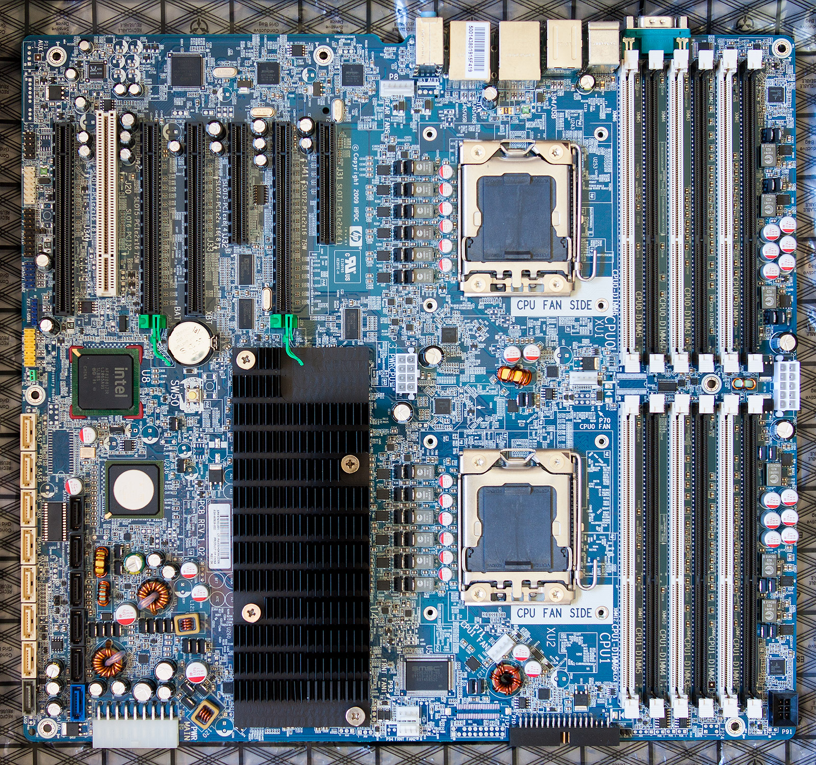
click for larger
Excitement quickly turned into a daunting realisation that I may have bitten off more than I could chew. The board is massive. It will not fit into any ‘normal’ PC case, not even an EATX tower case. The mounting screws will not mate with any of the ATX holes in a motherboard tray. The large ATX power connector is non-standard. The CPU fan headers are non-standard. There’s a separate power connector for the memory banks with a proprietary connector. The list goes on…
Clearly this is a server motherboard adapted only slightly to fit into HP’s proprietary case with HP’s proprietary power supply and cooling system. Buyers of the Z800 certainly received their money’s worth compared to an anonymous box filled with generic parts.
I’m not one to give up in the face of a technical challenge and besides I’d just forked out a hundred notes on the board so the rest of this article will go through all the steps in detail that you would have to do in order to get one of these beasts up and running yourself. There’s no cheaper way to get 12 cores of Xeon power under your desk.
The BIOS and CPU compatibility
The Z800 board comes in three different revisions, indicated by the AS# number printed on the white sticker located directly below the big black chipset heatsink.
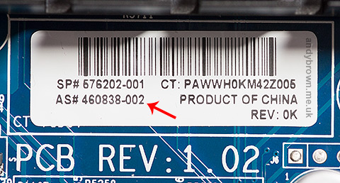
The revisions are indicated by 001, 002 or 003. As you can see from the image this board is an 002 revision. The executive summary to what I’m about to explain is that if you have revision 001 or 002 then you can officially use only Xeon X55xx CPUs. If you have the later 003 revision then you can use either X55xx or X56xx CPUs.
The issue is the BIOS bootblock. It’s physically write-protected within the BIOS and does not get upgraded when you flash the BIOS. So if you have one of the earlier revisions and you flash your BIOS then the X56xx CPUs will be recognised but the bootblock may fail to get that far and you could be presented with a black screen and a POST failure when you power up.

The key is the bootblock date shown in the BIOS System Information screen. A date of 11/10/09 is required to support X56xx CPUs.
Note how I’ve used the word officially a few times back there because the fact is that it might work. Word on the HP forums is that the behaviour of an earlier revision flashed up to the latest BIOS and used with X56xx CPUs ranges from ‘works for me’ to ‘sometimes won’t boot’ to ‘total failure to POST’. The worst issues seem to be with dual-CPU configurations. Later on this article I’ll go through my own setup and experiences.
The case
We need to start with a case for this thing and like I said, even the largest ‘normal’ tower case will be too small. You need an HPTX format case. There aren’t many of these and the one I chose was the Nanoxia Deep Silence 6.
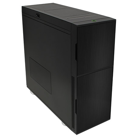
I got it from Quiet PC in the UK and managed to grab a B-grade bargain at £139, that’s a £50 reduction on the full price and I couldn’t tell what made it B-grade because it looks perfect to me. Maybe I have lower standards than most.
I can confirm what the online reviews say when they describe this case as being massive. It is indeed, truly huge. I expect that if it were hollowed out then I could fit my current Fractal Design tower case inside it. It swallows the Z800 motherboard as if it were designed for it. Result.
Modifying the case to hold the motherboard
I mentioned before that the motherboard mounting holes do not match up with the corresponding holes in the case’s motherboard tray. I had to drill and tap new holes for enough screws to hold the board safely with its heavy load of up to two CPUs with large heatsink/fans attached.
This is a fiddly process. Before starting I fitted a small random PCI card into the motherboard and used it to work out exactly where the board needed to be so that the cards lined up with their fixing holes on the side of the case. I used a 2.8mm drill and then tapped the holes out to the correct imperial 6/32 size for motherboard mounting posts.
The hardest part is offering up the motherboard to the tray and accurately marking where to drill. You have to be very accurate or the posts won’t line up with the holes and you only get one chance. A slow, controllable drill that won’t skid is essential and it needs to get into some confined spaces.
Eventually I got all the holes drilled that I thought I could get away with and the board is held securely clear of the base of the case.
This is by far the hardest part of the job and even with all my careful measurement and drilling my expansion cards are slightly bent in their slots due to a couple of millimetres of misalignment. Oh well, at least they’re held tight! If I were to do this again I would probably drill wider diameter holes in the motherboard tray to allow a small amount of adjustment. I’d then use wide washers on either side of the tray, a standoff above the upper washer, a screw through everything and a locking nut at the back of the tray.
The power supply
The original Z800 comes with a power supply engineered by HP to fit the genuine HP case. It is, of course, totally incompatible with a standard PC case so I needed a standard PC power supply that met the requirements of the board.
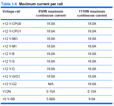
The HP power supply distributes the main 12V output across 8 different rails, each with a maximum delivery of 18A but with a combined output ceiling of 70A for the 850W unit and 92.5A for the 1110W option. I have no way of knowing how much will actually be drawn by each rail so it’s safest for me to buy a single rail unit with a nice high overall amperage.
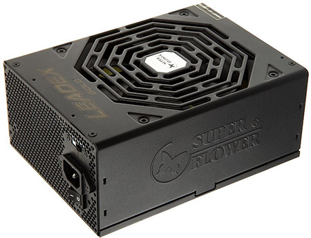
I plugged my prospective peripherals into an online PSU amperage calculator and it came out with a recommended 750W supply for dual 130W TDP processors, four 15K SCSI drives, an SSD and an ATI 7970 graphics card. The power supply is so important to the overall stability of the system that I don’t skimp on it but, as usual, I’m determined to get the best deal I can. After much research I bought a SuperFlower Leadex 1000W (80+ gold) supply from Overclockers UK on one of their ‘this week only’ deals for £110. It’s very highly thought of and should be more than enough for this system.
Custom cabling
I mentioned before that some of the board power connectors are non-standard, in fact only the 8-pin EPS connector has a standard pinout and fitting. The main ATX power connector and the memory power connector are custom HP designs. Thankfully the Z800 service manual gives the pinout of these connectors so it’s not hard to make up some custom cables to do the job.
The main ATX cable
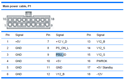
The above image is taken from HP’s service manual for the Z800. It shows the pinout of the power cable, taken as you hold the cable and look at the connector. The first issue is the physical cable itself. Each of the pins in the connector is physically keyed with either a square or a slightly rounded socket and there are only 18 pins.
Luckily the order and shape of the pins is identical to a standard 24-pin ATX power cable leaving 6 pins unused at one of the ends. To solve the physical cable issue I bought an ATX power cable extender on ebay for a few pounds and simply sliced off the unwanted pins with a dremel and sanded it to leave a nice finish. The power supply’s standard connector will plug into the unmodified end of the extender and the modified end will go into the motherboard’s socket.
The second issue is the pinout. It’s not the same as the standard ATX pinout at all. To solve this issue I cut the wires of the extension cable around the center and simply remapped them to match the standard by soldering the ends together.
Most of the names in HP’s pinout have an obvious mapping to the ATX standard but there are some that need an explanation. The +12V and V12 lines are all the same and need connecting to the +12V ATX line.
When mapping the five Z800 12V pins to the two ATX PSU pins make sure that you either connect together all Z800 pins to both of the two ATX pins or you make sure that the two V12_S pins are not connected to a single ATX 12V pin. According to table 1-5 in the reference PDF V12_S is the line that powers the slots and high power graphics cards can draw up to 75W each from the slots. The second ATX 12V line was added to support these cards and if you were to connect the V12_S lines to a single wire and then add a high-power graphics card then it may not work, or you may start a fire.
The PSU_ID line is an unknown. My guess is that it was designed to allow HP to detect which of the PSU models were fitted and maybe display it somewhere. I’ve no idea whether this should float, or be pulled low or high so I started with the easiest option which was to let it float by simply tying it off with a piece of masking tape.

click for larger
The memory cable
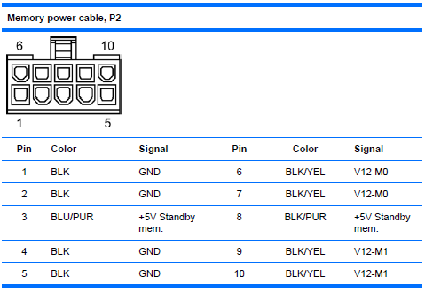
The Z800 has a whopping 12 banks of DDR3 memory available and the designers have, in common with many server motherboards where stability is paramount, opted to give it its own power supply. Again the HP service manual comes to the rescue with the pinout of the connector as you look at the cable.
The connector type is the same as the main ATX power cable and again we are very lucky that the keying of the connector shape matches up to one end of the standard 24 pin ATX cable. I purchased another ATX extender cable and sliced off the part of the connector that was not required.
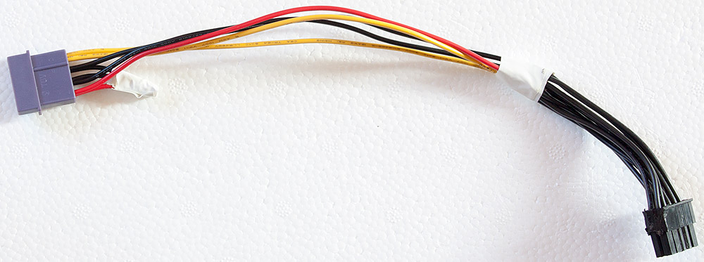
click for larger
To hook it up to the main power supply I took a Molex ‘Y’ splitter of the type that you often get for free when you buy case accessories and cut off one of the plug ends. Molex cables have GND, 12V and 5V lines which is all I needed to wire up my hacked cable. It doesn’t matter that many of the 12V wire into one from the Molex connector because these lines don’t carry a high current. The unused wires were tied off with insulating tape.
Since the publication of this article a reader sent me a link to a seller on the Chinese TaoBao shopping site who offers a custom made cable set that does everything all my hacking does. If you have access to TaoBao then I’d recommend that you buy one instead of going through the hassle of making one like I did.
Another update. The cables previously only available on TaoBao are now available on Ali Express. Search for “z800 power adaptor” on the Ali Express website to find them. I’ve bought a few things from Ali Express sellers in the past and have found the experience to be generally the same as buying from Chinese sellers on ebay.
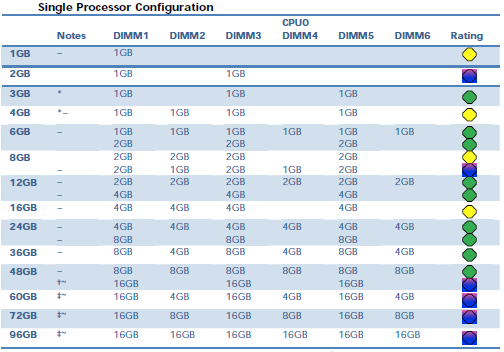
The memory
Because this PC is so closely related to a server board it requires registered PC3-10600P 1333MHz DIMMs. A wide range of configuration options is available up to a massive 192Gb when in dual-CPU configuration, explaining the presence of a separate power socket on the board for the memory banks.
After much scouring of the internet I scored 24Gb of original HP memory for about £60.
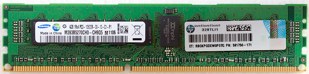
click for larger
This first lot of 24Gb will do fine for my initial tests. When I come to install the full complement of two Xeon processors then this board’s design means that I can either keep the 24Gb configuration (12Gb will be installed per processor) or I can double up to 48Gb by populating every slot with a 4Gb DIMM.
The original HP design features a large heatsink/fan unit dedicated to just the memory banks. Obviously HP have to design a system that will cope with the full load of 192Gb of memory potentially sharing a case with dual graphics cards and dual 130W TDP processors and a whole raft of hard disks. My more modest target of 24Gb of RAM and a single graphics card means that I’m not going to need a dedicated memory cooling system.
The CPU
At this point it would be a fairly big risk for me to go out and buy the 3.33GHz X5680 hex-core Xeon that I actually want because there’s still a possibility that this whole system will not work and I’ll be left with an expensive CPU to sell on. So for testing purposes I did a bit of bottom-feeding on ebay and scored a brand new quad-core 2.13GHz E5506 for the princely sum of £1.43, less than the cost of a power cable extender. Crazy.
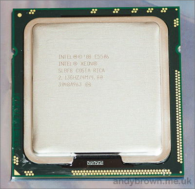
Unloved, the quad-core E5506
The heatsink & fan
HP’s designers must have fallen asleep here because the original HSF is actually rather close to being a standard fit. The only real problem is that it comes with an odd 5-pin fan connector instead of the usual 4-pin. The extra pin is labelled TACH2 and from doing a bit of research it seems that on many boards HP have just grounded the extra pin. The other issue is the price. Even used units are very expensive for what they are so I’m going to go with a standard unit.
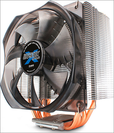
The HSF that I bought is the Zalman CNPS10X Optima, costing just £16.50 on Amazon. What’s really great is that no modifications are required to fit it to the board. The board already comes with a backplate ready to accept the screws that go into the fan assembly. All I have to do is screw it down on top of the CPU.
Or so I thought. The screws supplied with the Zalman are not the correct gauge for the thread on the backplate. It’s very close but if you pull on them then they’ll slip out. Not good and potentially fatal to the CPU if it were to let go in operation. I don’t know who to blame here because the thread on the backplate is a standard gauge – normal computer case screws are a perfect fit. Anyway I found some long-ish replacement screws and just fastened it down reasonably tight and as even as I could make it.
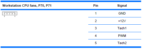
I connected the 4-pin Zalman fan connector to the first 4 pins on the CPU fan header, leaving the mysterious ‘TACH2’ pin floating. Hopefully the BIOS doesn’t care about this pin.
Edit: After upgrading to the X5680 Xeon I started to get a POST warning about having a high powered CPU and a low-powered CPU fan so maybe the fifth line is actively driven to a level by HP’s official high-speed fan to indicate that it’s compatible with the 130W Xeon’s. Anyway, there’s nothing low spec about the Zalman so that warning is duly ignored.
The front panel connectors
Every motherboard has a bank of pins for connecting up the power switch, hard disk LED, power LED etc and the Z800 is no different. On this board it’s the bank of pins labelled ‘P5’. Now here we have a problem because the service manual does not list the pinout for this bank.
I scanned the internet for clues, even searching google images to try to find an internal shot of the workstation where I could see the wiring. No luck. The nearest I came was this post on one of HPs forums that related to a similar but not the same workstation board. Just in case that post disappears off the internet, here’s the pinout:
Pin 1 = Hard drive clear plastic lens bottom LED  (which shows HD activity)… white wire
Pin 2 = Frosted lens top LED  (solid or blinking green LED)  (one wire of front panel dual-color LED)… red wire
Pin 3 = Hard drive clear plastic lens bottom LED (may be ground end)… green wire
Pin 4 = Frosted lens top LED Red (solid orange color LED)  (other wire of front panel dual-color LED)… black wire
Pin 5 = No wire attached in xw6400.  May be ground.
Pin 6 = Front panel switch for power on/off… thick white wire attached..  May be the positive.
Pin 7 = No wire attached in xw6400
Pin 8 = Front panel switch for power on/off… thick white wire attached.  May be the ground.
Pin 9 = No wire attached in my xw6400.  May be +5V
Pin 10 = Key (no pin on motherboard header; plastic filling the #10 hole in the receptacle)
Pin 11 = No wire attached in xw6400.  Has gray wire of ambient air temperature thermisitor attached in xw6600 cable
Pin 12 = No wire attached in xw6400.  Has brown wire ofambient air temperature thermisitor attached  in xw6600 cable
Pin 13 = Orange wire, but not used in my xw6400.  For hood sensor connector.  May be ground.
Pin 14 = Orange wire, but not used in my xw6400.  For hood sensor connector.
Pin 15 = Key (no pin on the motherboard; plastic filling the #15 hole in the receptacle)
Pin 16 = Blue wire, but not used in my xw6400.  For hood sensor connector.
Pin 17 = Internal speaker +… yellow wire
Pin 18 = Internal speaker - … yellow wire
In the absence of anything better to go on I decided to give that pinout a try. At the very least I need the power switch to work, everything else is a ‘nice to have’.
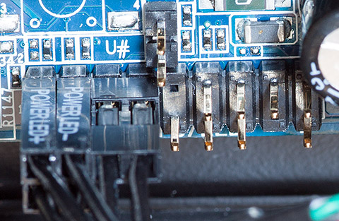
That’s what it looks like with the power switch, power LED and hard disk LED connectors in place. I’ve heard from someone else who’s working on one of these boards that the pinout for the internal speaker connector is also correct.
Testing
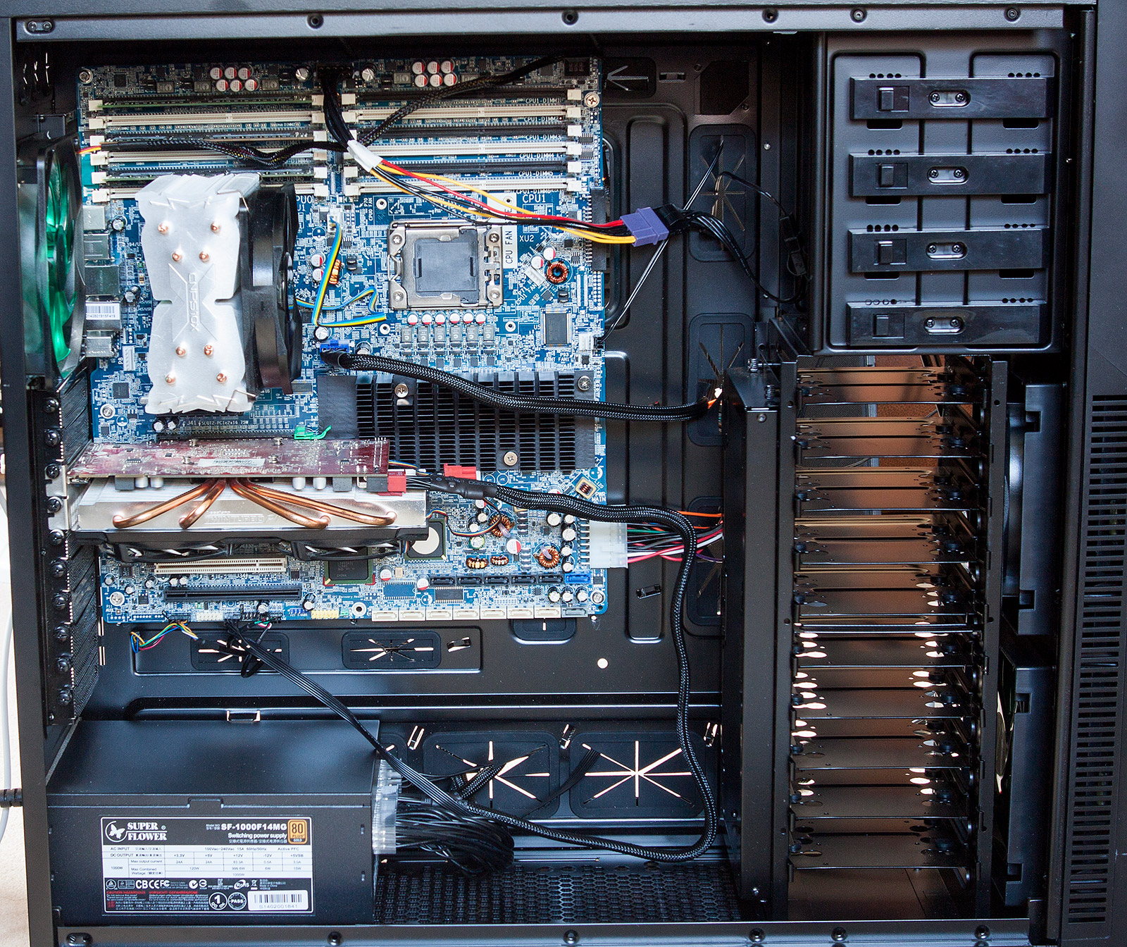
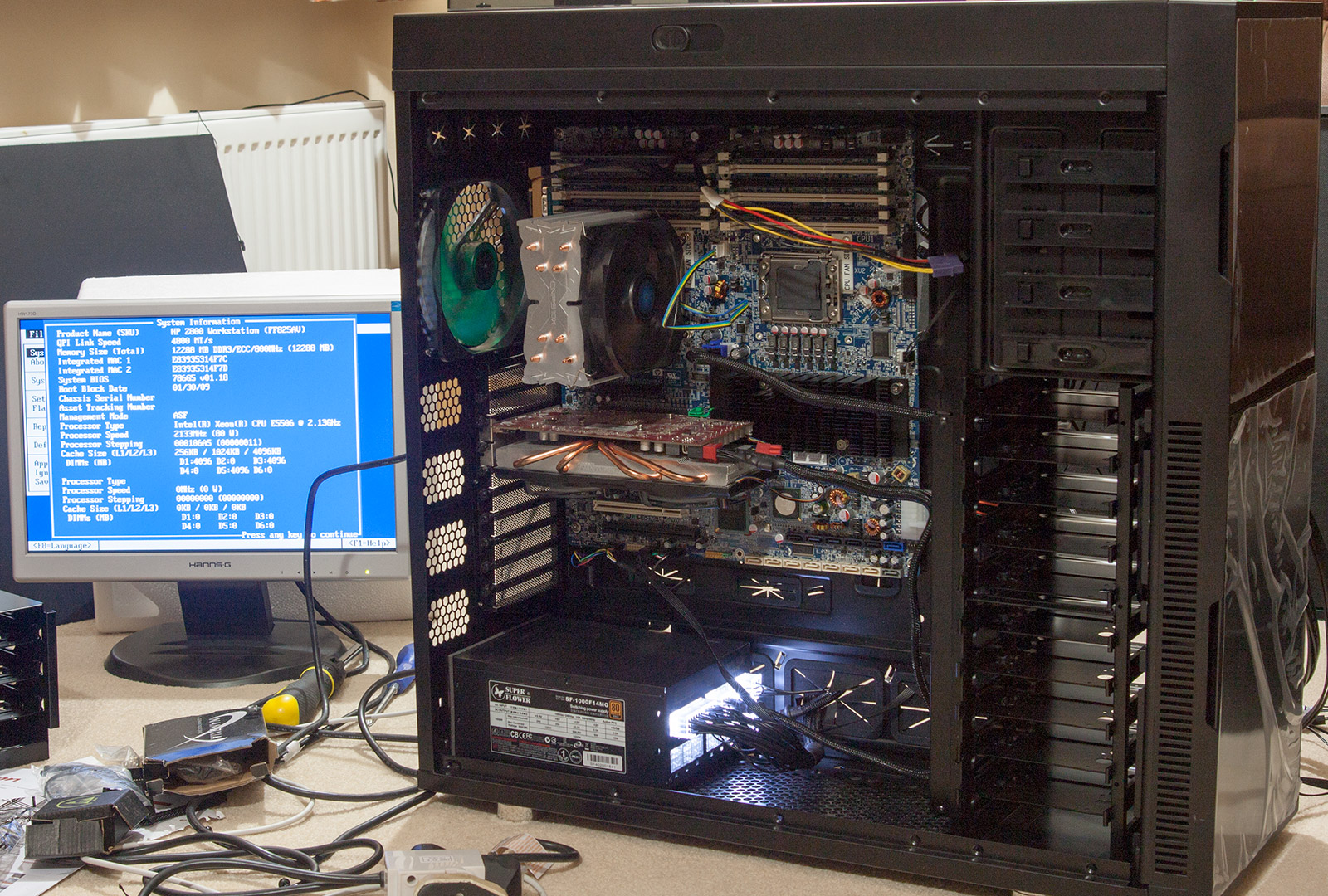
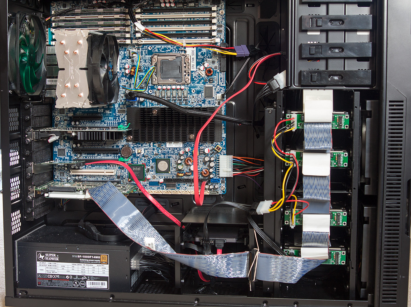
Now all my modifications are done, it’s time to put it all together in the case and do a quick test. You only need memory, a CPU and a graphics card to do a POST test on the board so I retrieved an old PCIe graphics card from storage in the garage and hooked it up to an old monitor for testing.
click for larger
The board actually looks quite normal inside that case but I can assure you that both the case and the board are very large indeed.
The moment of truth. Switch it on and see what happens.
click for larger
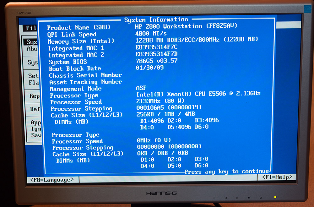
It works!
Everything seems to be OK. The power button and power LED connections are correct, all the memory is detected, the CPU is detected and the CPU fan is spinning. I went straight into the BIOS settings screen and had a look around. I noticed that the BIOS revision was behind the latest so I upgraded it to the latest version via a USB stick.
click for larger
The BIOS is able to to detect the CPU fan speed so I guess it doesn’t need that mystery TACH2 pin. There doesn’t seem to be anything that shows the model of PSU that it thinks is connected so I’ve no idea what, if anything, that PSU_ID pin was for.
Now we’ve got a good system it’s time to get some storage in there.
Storage
The Z800 board comes with a ton of SATA connectors and a SAS RAID controller manages at least some of them. The thing is, they are all SATA-2 3Gb/s and I’m planning on connecting a Samsung EVO 840 240Gb SSD as my primary OS and programs disk.
The Samsung SSD is a SATA-3 6Gb/s device and although in practice nobody can honestly tell the difference between 3Gb/s and 6Gb/s in real-life usage it would be nice to have the primary SSD on a full-speed bus. The answer is a cheap PCIe card with a couple of SATA-3 connectors on it.
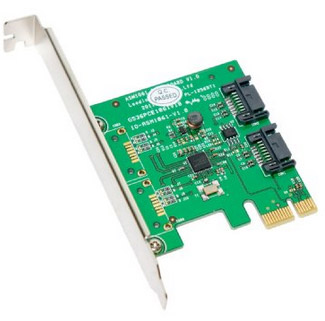
I picked this ‘Syba 2 Port SATA 6Gbps PCI-Express x1 2.0 Card’ up on Amazon for less than 20 quid. I picked it because in the reviews there was a Z800 user who’s using it successfully as a boot device which is exactly what I want to do.
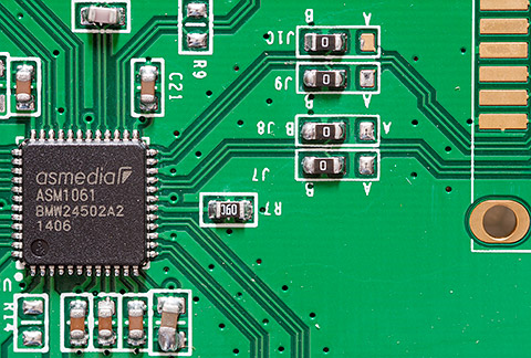
They’re using the popular Asmedia ASM1061 chip in a QFN package as the SATA controller. There’s a bit of wonky soldering on a few of the caps there but generally it looks fine. They’re using the same board layout for their SATA and eSATA products which explains the presence of the 0R bridging resistors being used as option selectors.
Working Specification
Now it’s all working I can move in all the rest of my peripheral ‘furniture’ and upgrade the CPU to the final specs. I picked up a Xeon X5680 on ebay for around £200 and thankfully it worked in my 002 revision board without any problems. I actually bought the X5680 before I found out about the issue with the BIOS bootblock and so I do consider myself one of the lucky ones. I think that if I hadn’t used the E5506 to upgrade the BIOS to the latest revision then I would have had a POST failure with the X5680 due to missing microcode for that newer CPU.
click for larger
I’ve got an 003 revision board on the way to me courtesy of ebay so when I do eventually decide to upgrade to dual Xeon’s then I’ll have a board that’s officially supported.
The rather ugly RAID configuration was ported over from my previous system. If anyone were building a new array today with this motherboard then it makes much more sense to use the onboard SAS RAID controller than the Ultra320 expansion card that I’m using.
Under Windows 8.1 with an ambient 20°C temperature all cores are idling at around 29°C. Stress testing with the prime95 application causes the cores to go up to about 58°C after which I got bored watching something that I’m never going to do in real usage and stopped it.
Notes, issues etc.
I did encounter some issues while assembling the full system with all my expansion cards. Here’s what I discovered and how I worked around each issue.
Attempting to install my XFX 7970 graphics card caused the biggest headache. It started OK then as soon as the Windows 8 start screen appeared the monitor signal was lost and I had to power off the computer. Worse, it would not POST afterwards. Worse than worse, restoring the previous graphics card also would not POST. I honestly thought I’d fried the entire motherboard.
However, some minutes later it all started working again with the previous card. I’m guessing that the XFX card somehow triggered a resettable overcurrent or heat-related fuse and a few minutes later the fuse reset. I’m now using a cheap Nvidia 210 single-slot card because I don’t play games so a power-hungry hot-running gaming card would do nothing except block useful expansion slots.
Installing the PERC 4e/DC RAID card caused the BIOS to complain on startup about being out of memory for option ROMs. This is another well documented complaint. The solution was to disable some of the unwanted onboard peripherals, something that also speeded up the POST process.
Samsung’s so called RAPID mode file system filter driver, which is actually just a write-back cache, causes random blue screens as-of version 4.4. Searching the internet shows that this is a common issue and since the SSD is plenty fast enough without dodgy drivers upsetting the stability I simply disabled RAPID mode.
Windows 8.1’s fast boot mode would sometimes cause the computer to do an immediate power-off as soon as the boot started. Fast-boot works a bit like hibernate mode where the previous state is restored from a disk file on boot. I couldn’t narrow this one down to any particular cause so I just disabled fast boot.
The PERC 4e/DC RAID BIOS screen uses the F10 key in some places to operate its menu system. It’s a well-documented problem that if F10 is used by your computer to enter its BIOS then F10 will not work inside option-ROM BIOS screens. The result was that I could not configure my RAID array. The solution was to use the megarc utility from LSI to configure the RAID options. For example, from an Administrator command prompt the megarc -newcfg -a0 -R5[1:1,1:2,1:3,1:4] -strpsz32 DIO WB RAA command would create a RAID-5 array using the SCSI disks on adaptor 0, channel 1, with SCSI ids of [1,2,3,4] using DirectIO, write-back and read-ahead-adaptive options.
You do get some warnings from the BIOS at the final stage of the peripheral initialisation.
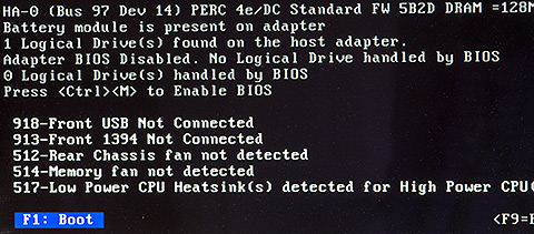
These warnings are just for informational purposes and do not affect the operation of the system. They can be ignored.
Update: the dual CPU upgrade
A month or so ago I replaced my 002 series motherboard with an 003 series that I found on ebay for a decent price. Given what we know about the limitations of the 001 and 002 AS# boards and dual-socket hex-core Xeon’s I thought it prudent to upgrade the board early with a future dual-socket X5680 configuration in mind.

That’s the bootblock date that you need to see in the BIOS system information screen if you want to install dual X56xx CPUs.
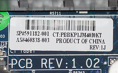
If you’re searching for boards to buy on ebay then make sure you get one that has the AS# number on the above sticker, the one that ends in 003.
The time had come for me to upgrade to dual X5680’s and so I lurked a bit on ebay and scored one for £175. That’s not exactly cheap; they seem to be priced better on the US ebay, but it was the best I could do. I also picked up a second Zalman CNPS10x Optima to match the first.
Fitting was quite easy. Instead of using the Zalman-supplied screws that I now know are a poor fit I screwed four standard motherboard mounting posts in to the board and then screwed the HSF ‘star’ shaped bracket down into the posts using normal motherboard screws. The posts provide just the right standoff from the board and screwing the fan bracket down into the posts is really easy.
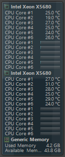
Open Hardware Monitor shows the loads and core temperatures.
click for larger
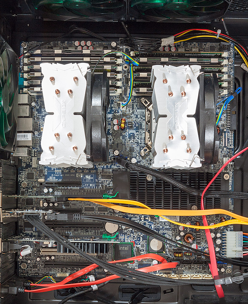
Here’s how it looks today. Dual X5680’s with 48Gb of RAM (I picked up another 24Gb for about £60 on ebay). Since I posted the original article I’ve made a few more changes to the configuration. The graphics card has been downgraded to a low power Nvidia 210. A USB 3.0 card has been added and hooked up to the case’s front ports.
That big black chipset heatsink gets very hot so I’ve mounted an internal 140mm fan blowing across it from the front to the back. You can’t quite see it in the above photograph unfortunately.
The hot and noisy SCSI array has been moved out into a cheap Dell 2850 server currently doing duty as a part-time NAS box with 4x146Gb and 2x72Gb drives that just happens to also have a pair of Xeons in it running Ubuntu Linux. In their place I now have a 240Gb Samsung and a 512Gb Crucial SSD for programs and data, respectively. They’re both hooked up to the internal SATA-3 PCI-e card. Being all solid-state is both quiet and power-efficient.
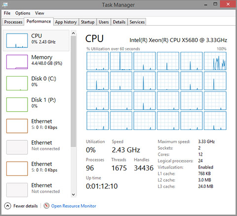
Hyperthreading is enabled so Windows task manager thinks that I’ve got 24 cores. I haven’t done any actual testing on the effectiveness of hyperthreading so I don’t have an opinion on it either way. Benchmarks on the internet seem to show a little gain in most circumstances so I’m leaving it on.
The Xeon series that I’m using supports Intel’s Turbo Boost technology which is an adaptive clock multiplier and divider combination that automatically raises the core clock frequency over the base by either 133MHz or 266MHz, depending on load. When idle it applies a clock divider of 2 to run the cores in ‘eco’ mode.
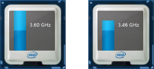
The images shows the two turbo modes of the X5680. If a single task is demanding high core utilisation then I’ll see 3.6GHz. Pretty much all other load causes it to run at 3.46GHz and doing nothing much, like typing this article, runs it in eco mode (1.6GHz).
It’s a testament to the cooling performance of aftermarket coolers such as the Zalman CNPS10x that even during a 12-core Premiere Pro video rendering session of one of my YouTube videos that the CPU cores never exceed the low to mid 60C range and therefore the entire rendering session is achieved at 3.46GHz. I don’t think I’ve ever seen it clock down to the standard 3.3GHz.
Feel free to leave a comment below, or maybe you’re building a Z800-based system yourself and would like to stop by the forum to share your experiences.
Update: 003 BIOS image available
Here’s one for the hardcore hackers out there that are willing to physically rework their board to attach an 003 BIOS chip. I’ve saved out my 003 BIOS image using the linux flashrom utility. If you’re interested in this level of hardware hackery then head on over to the forum where you can download the image.
The inevitable disclaimer applies here. It’s entirely up to you to verify that this image is all that you expect it to be. If it turns out to be bad then please don’t blame me, although I would like to know about it.
BIOS PCB layout
Here’s some more information that may help out the brave hackers amongst you. We now know that the BIOS is an SST (Microchip) SST25VF016B 16Mbit device and the datasheet is readily available. Here’s an image of the BIOS chip on my 002 board; it’s located down between the single PCI and the last PCIe slot.
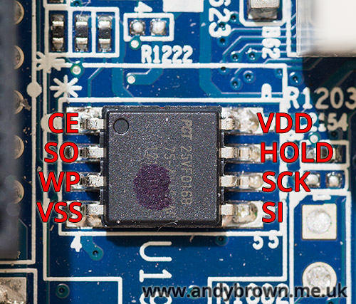
To save you digging out the datasheet I’ve labelled the function of each pin. If there’s to be any hope of reprogramming this IC in-circuit then pin 3 (WP = Write Protect) must read high. I tested the resistance of this pin between VSS and VDD and unfortunately it read about 13KΩ against both VSS and VDD so it’s not as simple as a straight pull-up or pull-down.
Further down on the board near the SAS connector there’s a soldered-in footprint labelled SPI Recovery Header header.
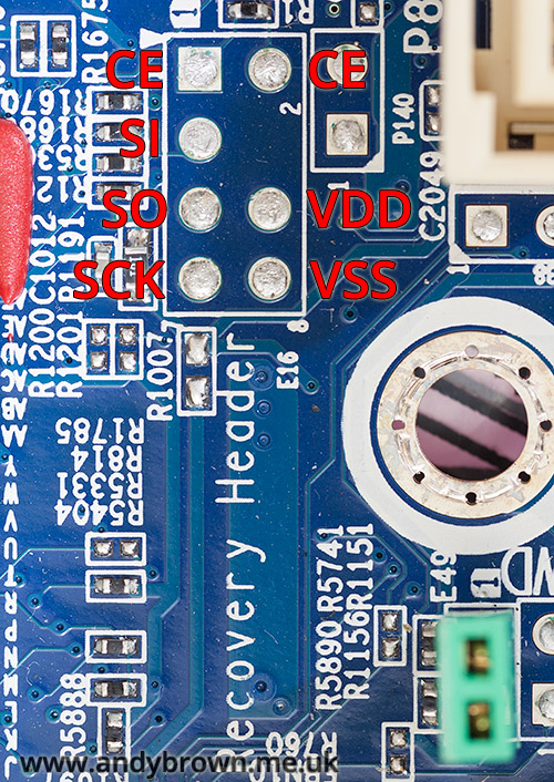
I got my multimeter out and tested continuity between the BIOS pins and the pins on the footprint and was able to determine the mapping labelled in the image above. Unfortunately WP was not mapped to any of these pins.
A reader over at this forum thread was interested to know if the green jumper E49 that you can see down at the bottom right removed the write protection from the BIOS. Unfortunately it’s not linked to BIOS write-protection, it does in fact clear the BIOS password.
Update Sep 2016: CPU fan replacement
My Zalman CPNS10x CPU fans have started to give up the ghost. I’ve noticed that they’re a bit noiser than they should be at idle and when Speedfan ramps them up they start to rattle. To give you an idea of what I’m talking about I made an audio recording.
Click here to listen to the Zalman fans
The recording device was placed close to the case and the microphone gain set on the highest setting. You’ll first hear the fans both ramp up from 30% to 100% in Speedfan and then the rattling starts. That’s the sound of the bearings wearing out. The deep resonance that you can hear on the recording is because of where I’ve placed the recording device on the case and is not audible in real use. Seriously, that would drive me crazy.
I decided to replace them with a pair of Nanoxia 1500rpm PWM fans because they get great reviews and don’t cost as much as Noctua’s which I consider to be great quality but overpriced for what they are. Today the replacement fans arrived.
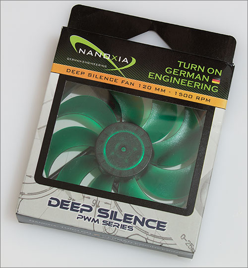
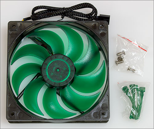
The box they arrive in is pretty much the same as every other fan you’ll ever buy. You get the obligatory set of four case screws and also a set of rubber anti-vibration mounts if you don’t want to use the screws. I have no use for any of those accessories so they’ll go in my parts drawer for future use.
Fitting the fans was a trivial matter, they’re held on to the heatsink with those slightly fiddly tension wire clips that go into two of the fan screw holes and then pull back into a slot on the heatsink.
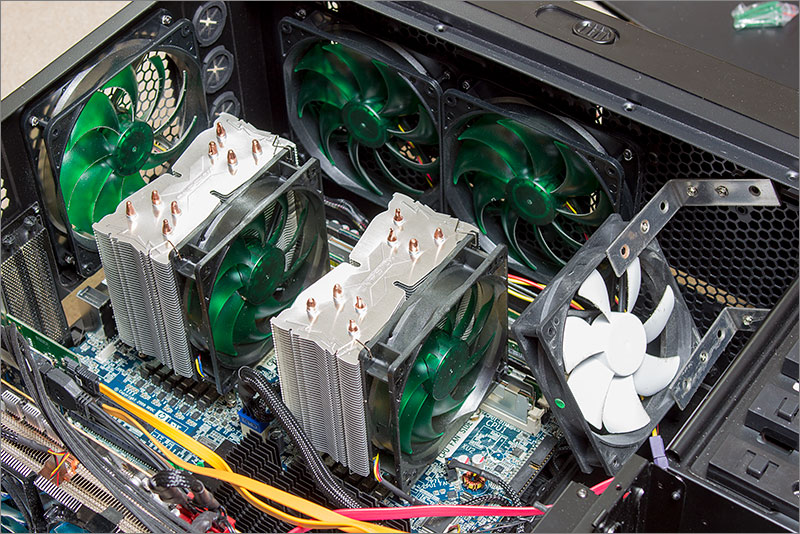
There they are, all nicely fitted and looking good with an almost full house of Nanoxia fans surrounding it except for that white interloper that I’ve rigged up to keep a breeze on the 48Gb of memory. Of course I took an audio recording after fitting the fans with the recording device in exactly the same place and with exactly the same levels as before.
Click here to listen to the Nanoxia fans
The difference is quite dramatic. Of course there’s no rattle from damaged bearings but the fans themselves are much quieter. You can hardly notice the ramp-up to 100%. The maximum RPM of these fans at 1500rpm is slightly lower than the Zalmans at 1700 but they are in the same ballpark so I think that the comparison is a fair one.
Update July 2020: Chinese PSU adapter cables
Earlier in this article I stated that pre-made adapter cables for connecting an ATX PSU to the Z800 motherboard were available on ebay and AliExpress. Recently I’ve been informed by a reader that some of these cables are incorrectly wired up. To quote from the email I received:
Could you consider adding a footnote in your article (for the more novice builders among us) that hints that some of these cables are wired incorrectly, with the purple +5VSB and gray PG/PWROK in the wrong place? Another user, lukew, has pointed this out in a post as well: ‘I bought them leads and the PS_OK and 5Vsb pins were reversed’. He hinted at the same issue in another post, but there wasn’t as much details on the problem: ‘I ended up adapting an ATX supply using some leads from China (which were made incorrectly)’.
I ended up trying a number of different PSUs of various wattages etc before I went back to checking the cable again, and it was indeed wired incorrectly as pointed out above. Just thought this might be helpful to stop some readers pulling their hair out, or worse: giving up on the project!
Thank you to Tom Ó Briain for pointing this out.