Tags
Related Posts
Share This


Project Difficulty
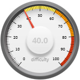
- All components are commonly available.
- The smallest IC pin pitch is 0.5mm
- The LT3042 has a hidden pad underneath the body
- The smallest discrete component is 0603.
- All components are on the top-side of the board
Recent Posts
Process automation: temperature sensing
My previous article documented how I designed and built a PCB that hosted three relays and a triac that could be mounted inside a PC case and connected up via the USB bus for host control using simple commands.
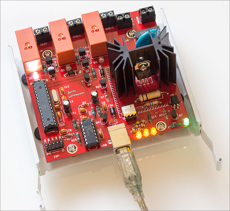
The relays and triacs board
That board is of course the output part of the system, responsible for executing the decisions made as a result of reading the inputs and executing control algorithms. Today’s article will document the development of the temperature sensors board used to sense the environment and provide the inputs to the system.
Temperature sensor technology
The first decision that I need to make is which technology to use for sensing temperature. I need a working range of 0 to 100°C and an accuracy of better than 1°C within the ranges of 60 to 70°C and 18°C to 22°C. The first of those ranges covers where brewers mash their grains and the second range is where fermentation is performed. Different characteristics in the finished beer are obtained by accurately controlling the temperature of those two processes.
Many technologies are available that differ in operating range, linearity, accuracy and stability. I had a look around at the availability and type of probes available for the different technologies and came up with the following summary.
Thermocouples
Thermocouples are subdivided into types differentiated by the type of metal junction at the hot end (J, K, N, E, R, S, T, and B). They can measure temperatures from as low as –265°C to over 1800°C. Thermocouples generate a voltage as a function of the temperature difference between the tip of the probe and the electrical connection on the PCB (the cold junction temperature).
Long stainless thermocouple probes are available
The K-type is the most commonly available thermocouple with a working range of –200°C to 1372°C. It’s easy to implement on a PCB thanks to all-in-one ICs such as the Maxim MAX31855. Unfortunately the standard accuracy of ±2.2°C isn’t good enough for me. The T-type would be much better for my application with a range of –250°C to 400°C and a standard accuracy of ±1.0C.
If I were to select a thermocouple as the best-fit technology then it would be a T-type.
NTC and PTC thermistors
As the name suggests these type of sensors are simply a resistor that changes value with temperature. An excitation current is applied to the sensor and a ratiometric measurement is made. Once the resistance is known an equation or lookup table can be used to convert the resistance to a temperature.
The accuracy of a thermistor can be very good. If carefully designed and calibrated then an accuracy of ±0.2°C is possible. The issue that rules this technology out for me is that the operating range is typically -40°C to 85°C. I need to measure up to the boiling point of water, around 100°C depending on your altitude amongst other things.
RTD
The resistance temperature detector (RTD) is a type of thermistor where the element is a length of wire wrapped around a core that’s often made of glass. The most common type is the platinum RTD and of the platinum types the PT100 is the most commonly used. PT100 means that it has a nominal resistance of 100Ω at 0°C.
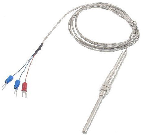
Long stainless PT100 RTD probes are common
Platinum RTDs have excellent accuracy, linearity and long-term stability. In the range that I care about the cheapest ‘Class B’ probes offer accuracy of ±0.5°C. Class A probes reduce this error to just ±0.25°C.
The drawback to RTDs is the cost. Both the measurement circuitry and probes obtained from a quality source, i.e. not ebay (see later) are priced comfortably in excess of thermocouple or NTC thermistor probes. Nevertheless, this is a cost I can justify and it places RTDs at the forefront of the technology choice for my application.
Digital sensors
In recent times sensors such as the Maxim DS18B20 have emerged that combine the sensor and the conversion circuitry into one small integrated package.
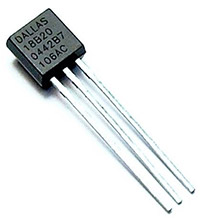
Maxim bought Dallas…
These sensors are small enough to be completely integrated into a probe. All the user has to do is connect up the probe wires to a digital MCU and read out the temperature values. It really could not be easier.
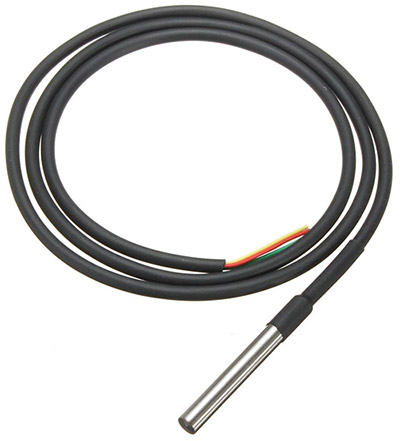
This probe style would work if placed in a thermowell
This is a compelling proposition since Maxim claim sub-1°C accuracy and the ease of integration is unmatched. What put me off this option is that good quality (not ebay) long stainless steel probes are not available. With all the technology embedded into the DS18B20 it shouldn’t matter too much if the probe is sourced from an unknown shop in China but I would still be left open to the possibility of the DS18B20 inside being a fake or the probe material not actually being food-grade stainless steel. For these reasons I decided not to use this new technology.
The winning technology
It’s the PT100 RTD. The best combination of accuracy, linearity and long-term stability won the day. It also helps that I know this is the technology used in commercial breweries because an electrician relative of mine fitted out a small craft brewer’s setup. It’s going to cost me more than any of the other technologies but I don’t mind since this is the part of the system that I need to get right. If you can’t trust your inputs then the rest of your system is making decisions based on faulty data.
Selecting a converter
To get the most out of my RTD probe the conversion circuitry needs to be carefully designed. A very small excitation current is applied to the sensor and will ultimately be converted to a digital value using an ADC. All of the components in the signal path need to be of the highest quality and the supply voltages need to be noise-free and accurate.
All-in-one measurement and digital conversion ICs are available and I decided to use one of these rather than try to role my own from discrete components and run the risk of introducing sources of error that could take me ages to isolate and eliminate.
Maxim offer the MAX31865 in an annoying QFN package and it’s available quite cheaply from Farnell. I’d need two of them for the design that I’m planning but this is a good option.
Linear Technology offer the LTC2986 in an easy to work with quad flat pack package. In fact this IC can handle multiple types of sensor technology and lots of probes attached simultaneously. The only drawback is that it’s quite expensive at around £25 plus VAT from Farnell.
After careful consideration and much reading of datasheets I chose the LTC2986. Despite the higher price it was the excellent datasheet, the customisation options and Linear’s reputation for producing the highest quality analog components that won me over eventually. At the price I’d better make sure I get this design right the first time or I’ll be spending more time than I’d like with my desoldering braid!
Design parameters
Now I know the conversion technology and the IC I’m going to use to do the conversion I can come up with the features that I’d like to have on my board.
- Up to two attached 3-wire PT100 RTD probes.
- On-board continuous temperature display using 7-segment LED.
- USB attachment to the host PC in the same way as my relays and triacs board.
Schematic
I translated my design parameters into a proposed schematic, and here it is.
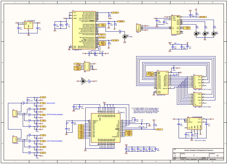
Click on the thumbnail to see a full-size PDF. Let’s take a look at the different sections of the schematic in more detail.
The power supplies
This one presented a few challenges due to the variety of acceptable supply voltage ranges of the different ICs on the board. Power comes in on the USB bus and that can range between 4.6V and 5.25V. To satisfy the parameters of the MCU, USB-to-serial converter, LTC2986 and the LED driver I decided to operate the board at 4.0V. Even though all the ICs on the board will run at the USB supply voltage I wanted to run the LTC2986 from a dedicated ultra-low noise regulator which meant that there would be some degree of dropout voltage that would affect the high/low levels of the digital lines connected to the MCU. For that reason I compromised on 4.0V across the board.
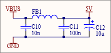
The USB power supply is notoriously noisy and I wrote an article on that a while back. This simple LC filter is designed to remove some of that noise.
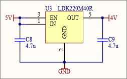
The first LDO regulator is the fixed 4.0V version of the ST Micro LDK220. It can provide up to 200mA and will be used to supply everything apart from the LTC2986.
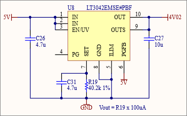
The second regulator is a rather special one. The LT3042 from Linear Technology is an ultra-low noise LDO designed to supply sensitive components such as an ADC. In my design it’s used as a dedicated regulator for the LTC2986. The 40.2kΩ resistor sets the output voltage to a nominal 4.02V.
The package is a nice and easy MSOP with the only pain being the pad on the bottom that needs to be soldered to the board. It’s quite common to see these on high-end regulators because they provide a good large ground connection as well as a useful heatsinking capability.
The USB-to-serial IC
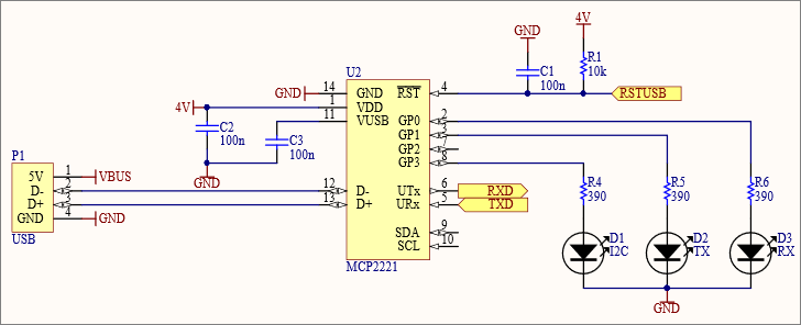
Just as with my relays and triacs board I’ll be using the Microchip MCP2221 USB-to-serial IC in a nice and easy DIP package. It’s resposible for presenting a USB CDC device to the host PC and translating to a 9600 baud UART that gets connected to the MCU.
The MCU
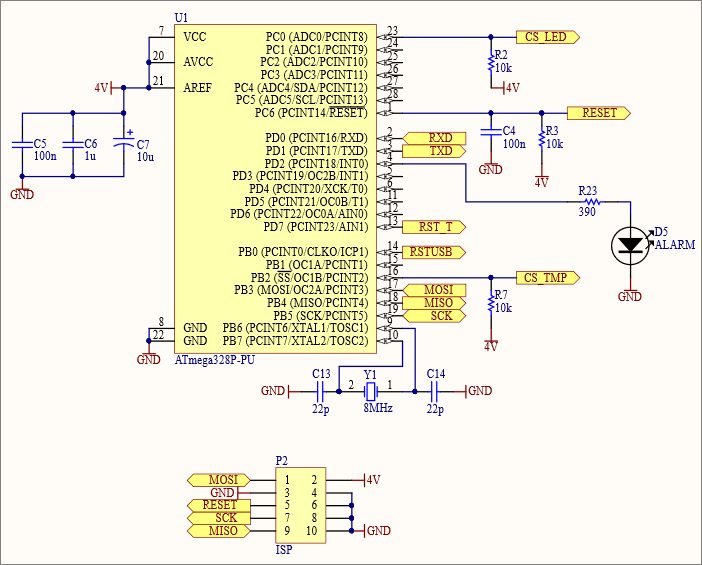
The venerable ATMega328P makes a familiar appearance again because it was a success in the relays and triacs board and so much of the firmware code can simply be a copy-and-paste job from there. It’s set up here to run from an external 8MHz crystal.
The GPIO lines are configured for SPI communication to the ISP header, the LTC3042 and the LED driver. Separate CS lines are used to ensure that only the correct device is listening at any one time.
I connected up a red LED to a pin and called it Alarm. The idea here is that I can control it as a visual indicator of a problem, for example a temperature threshold being exceeded.
The LED driver
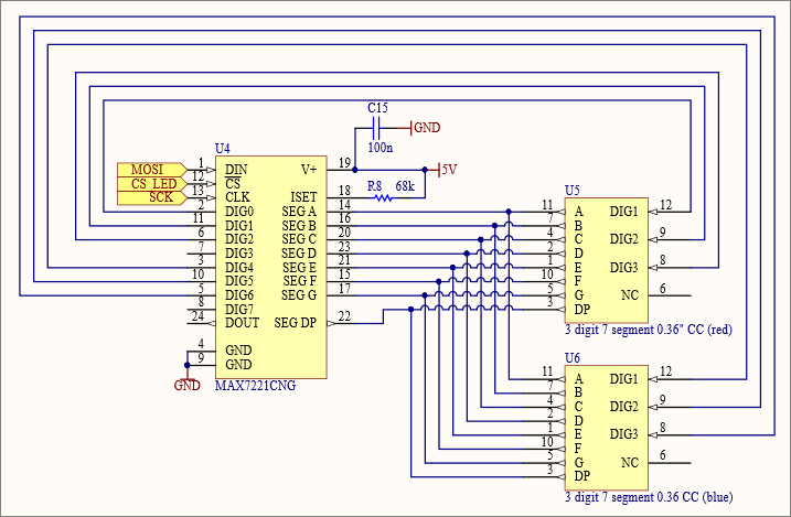
It’s the familiar MAX7221 in DIP format. I’ve used them before, I’ve got library code that I copy and paste and I bought a pack of ten on Ali Express for a very cheap price so it’s a no-brainer to include it here. It’ll be driving a pair of 3-digit common cathode LED displays.
The LTC2986
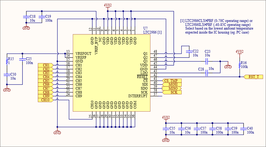
The LTC2986 provides ten input channels that can be configured according to the sensors that you plan to attach. With my two 3-wire PT100 RTDs I will need all ten channels. The remainder of the components are really just high quality X5R ceramic decoupling capacitors distributed according to the recommendations in the datasheet.
The probes
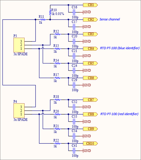
The probes are set up according to the example in Figure 39 in the datasheet 3-Wire RTD Kelvin Current Mode. This allows the use of ordinary input protection resistors that don’t need to be exactly matched.
3-wire RTD probes are probably the most commonly available type. One end of the sensor has a single wire attached and the other end has two. The end with two attached is used to sense the resistance of the leads and, as long as they are closely length matched, then that resistance can be cancelled out from the reading.
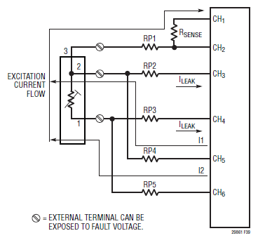
R10 is the sense resistor and this one really must be accurate. I selected a high quality 0.01% resistor that, at more than £2 each is probably the most expensive 1kΩ resistor that I’ll ever buy!
A great thing about the LTC2986 is that Linear Tech have provided free design assistance software that you can use to configure the probes that you’re going to use. Not only does it show you the wiring you need to do it also generates C code to set up the internal registers according to your configuration.
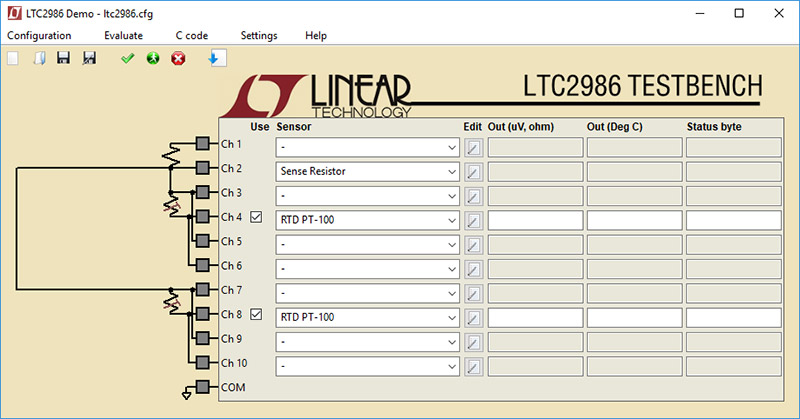
I love it when manufacturers do this. The LTC2986 has an excellent datasheet and I was pretty sure I knew what the probe wiring was going to be but to have the software confirm it and provide driver code was just a fantastic confidence boost and time saver.
Bill of materials
Here’s a complete bill of materials for this project.
| Designator | Value | Quantity | Description | Footprint | Farnell code | Note |
|---|---|---|---|---|---|---|
| C1, C2, C3, C4, C5, C11, C15 | 100n | 7 | Ceramic capacitor | 2.54mm | 2309020 | |
| C6 | 1µ | 1 | Ceramic capacitor | 5.08mm | 2112910 | [1] |
| C7, C12 | 10µ | 2 | Electrolytic capacitor | 5x11mm | 1902913 | |
| C8, C9, C26, C31 | 4.7µ | 4 | Capacitor | 0805 | 1759420 | |
| C10 | 10n | 1 | Capacitor | 2.54mm | 2309024 | |
| C13, C14 | 22p | 2 | Capacitor | 2.54mm | 1100369 | |
| C16, C17, C20, C21, C24, C29, C32, C33, C34, C41 | 100p | 10 | Capacitor | 0603 | 1759066 | |
| C18, C22, C23, C27, C28, C30, C35, C36 | 10µ | 8 | Capacitor | 0805 | 2320851 | |
| C19, C25, C37, C38, C39, C40 | 100n | 6 | Capacitor | 0603 | 1759037 | |
| D1, D2, D3 | Amber | 3 | LED | 3mm | [2] | |
| D4 | Green | 1 | LED | 3mm | [2] | |
| D5 | Red | 1 | LED | 3mm | [2] | |
| FB1 | BLM18PG221SN1D | 1 | Ferrite bead | AXIAL-0.3 | 2292304 | |
| P1 | USB B | 1 | USB B RECEPTACLE | 1177885 | ||
| P2 | 2x5 header | 1 | ISP connector | 2.54mm | [3] | |
| R1, R2, R3, R7 | 10k | 4 | Resistor | AXIAL-0.3 | 2329609 | |
| R4, R5, R6, R23 | 390 | 4 | Resistor | AXIAL-0.3 | 2329519 | |
| R8 | 68k | 1 | Resistor | AXIAL-0.3 | 2329546 | |
| R9 | 470 | 1 | Resistor | AXIAL-0.3 | 2329531 | |
| R10 | 1k 0.01% | 1 | Resistor | 0805 | 2112790 | |
| R11, R12, R13, R14, R17, R18, R20, R21, R22 | 1k | 9 | Resistor | 0805 | 2447587 | |
| R15 | 1 | 1 | Resistor | 0805 | 2447598 | |
| R16 | 100k | 1 | Resistor | 0805 | 2447551 | |
| R19 | 40.2k 1% | 1 | Resistor | 0805 | 2447658 | |
| U1 | ATMega328P | 1 | 8-bit AVR Microcontroller | DIP-28 | 1715487 | |
| U2 | MCP2221-I/P | 1 | Microchip USB-Serial | DIP-14 | 2434892 | |
| U3 | LKD220M40R | 1 | ST Micro LDO regulator | SOT23-5AM | 2435558 | |
| U4 | MAX7221CNG | 1 | LED Display Driver | DIP-24 | [4] | |
| U5 | 1 | red 3 digit 7 segment 0.36" LED | custom | [5] | ||
| U6 | 1 | blue 3 digit 7 segment 0.36" LED | custom | [5] | ||
| U7 | LTC2986ILX#PBF | 1 | Linear Tech temperature to digital converter | LQFP48 | 2629645 | |
| U8 | LT3042EMSE#PBF | 1 | Linear Technology LDO regulator | LT-MSE-10-EDP | 2475652 | |
| Y1 | 1 | Crystal Oscillator - ABLS-25.000MHZ-B2F-T | HC49 thru hole | 2063945 |
Notes
Some of the components have note numbers against them. The following numbered paragraphs correspond to a numbered note in the bill of materials table.
- 2.54mm parts can also be used if you carefully bend the leads outwards to fit the wider 5.08mm pitch.
- Any colour of 3mm LED will work and they’re cheapest on ebay.
- These 2.54mm headers are cheapest on ebay.
- The MAX7221 seems to be cheapest on Ali Express.
- Make sure you get the 0.36″ common-cathode variety. The red ones are easy enough to find but the blue ones are more elusive. I got mine from Ali Express. Search for item #32789229519.
PCB Design
The PCB design was given a jump-start by the success of my previous relays and triacs board. I set the extent of the board to a 10x10cm square and placed the mounting screw holes where they needed to be to match up with the footprint of a 2.5″ hard drive.
Next I knew I’d need a large area for the probes to attach. Probes designed to fit a specific hand-held reader will come with their own connector — often you’ll see some form of DIN or XLR connector used for this purpose.
General-purpose probes will either come with bare-wire termination or often you get spade-type connectors designed for screwing to a board.
I decided that spade or ring-type screw connectors would be the ones that I’d use. All I need to do on the board is provide screw holes of about 3.5mm with exposed copper around them to make a good contact with the screw connector.
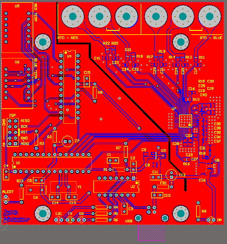
The top-right of this two-layer board is dedicated to the probes, the LTC2986 and the LT3042. This area is all surface-mount. In an attempt to eliminate the potential for digital noise to get into this area and interfere with the readings there is a split in the ground plane the forces return currents from the digital and analog sections of the board to stay separated from each other.
There’s a liberal sprinkling of vias to the bottom of the board, particularly around the decoupling capacitors. The bottom ground layer is unbroken by traces or components along the path to the ground pin of the USB connector.
The larger bottom-left section of the board is the digital stuff and indicator LEDs. There’s nothing really sensitive here so component placement is made for convenience and to match up with physical constraints. For example, the USB connector should be at the same side as it is on the relays and triacs board, the ISP header should be in an accessible position and the 7-segment LEDs should be at the edge of the board.
Instead of naming the probes something boring like #1 and #2 I decided to name them as ‘red’ and ‘blue’ and use red and blue 7 segment LEDs to display the readings. If the board gets mounted inside a PC as planned then I won’t be able to see the board readings unless I cut out a window or run the displays to the outside with wires but I can live with that.
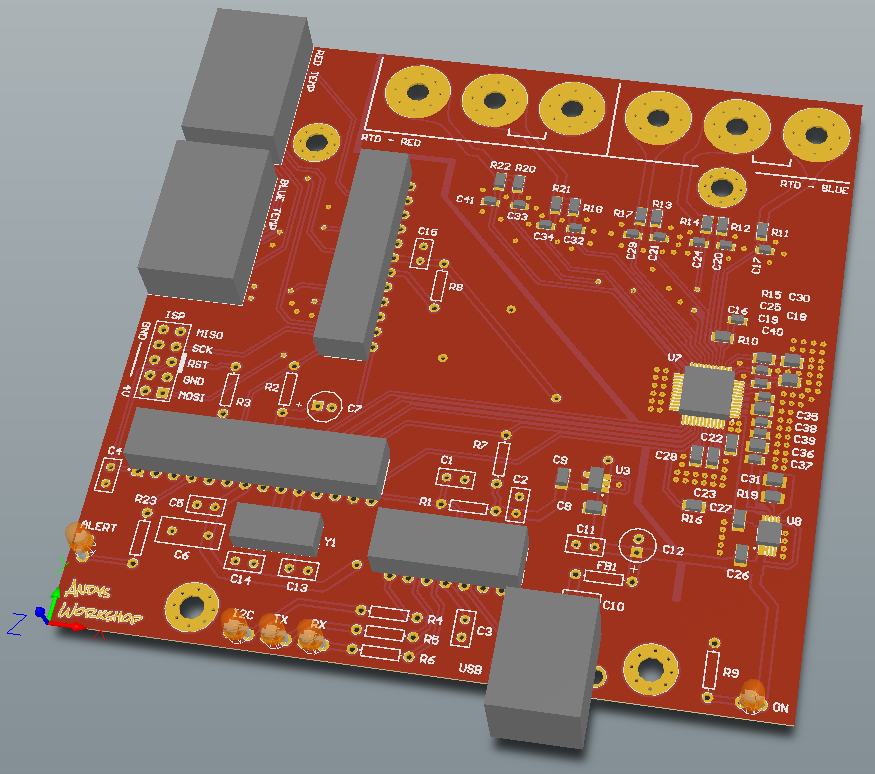
3D view is good for catching placement and overlap issues
Once I was happy that the design looked OK I sent it off to Seeed Studio for manufacturing because at the time they were the only ones offering the $4.90 deal for a pack of 10. I see that everyone’s got in on that price now which has to be a good thing for all of us.
Assembly
Before assembling the board I thought I’d better check out the precision 0.01% resistor with the best multimeter on my bench because I remember watching an EEVblog video where Dave got a precision resistor for his µCurrent project that turned out to be not so precision after all. After nulling out the test leads I got a measurement.
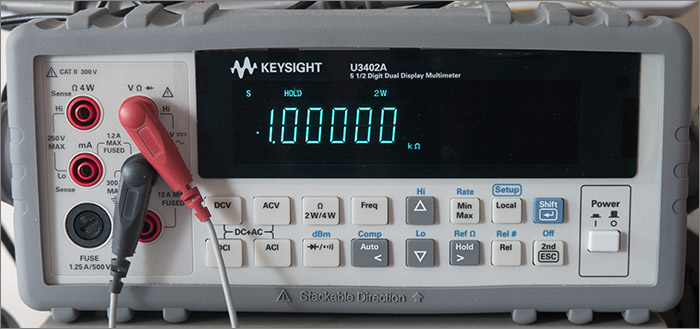
This is what 0.01% tolerance buys you
There’s certainly nothing wrong with that resistor. Hopefully it’ll age slowly enough over the years to come to not cause any measurement issues.
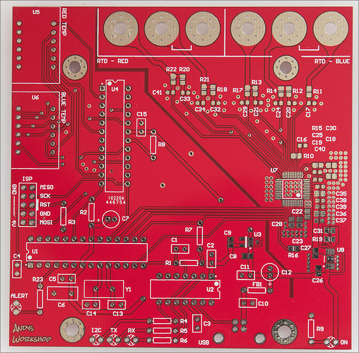
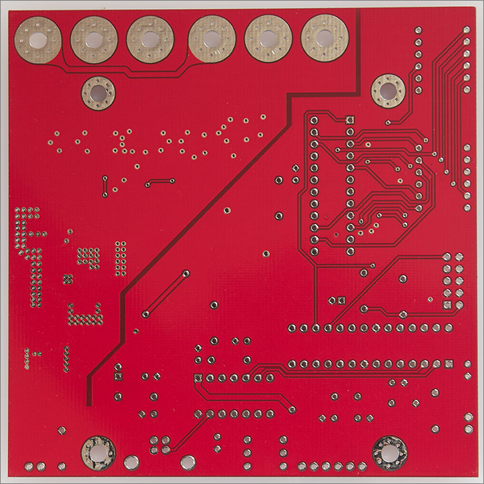
Here’s a picture of the front and back of the blank boards. No manufacturing boundaries are being pushed here so it was no surprise to find that the boards all looked to be perfectly made.
First I need to get the surface mount stuff out of the way. I tinned the pads with leaded solder so each one had a little bump of solder on it, applied more flux and placed the SMD components on to the little bumps.
Next I reflowed the board in my homemade halogen reflow oven. This was uneventful and worked perfectly. The solder bumps reflowed and all the components sat down on to the board. No post-reflow touch up was necessary. I was happy.
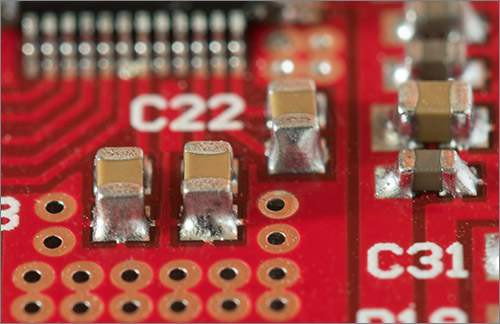
Reflowed solder fillets
With the surface-mount parts all in place I sat down with my soldering iron and did all the through-hole parts. I use sockets for my ICs just in case I mess up a prototype board design and need to recycle the parts for the next iteration.
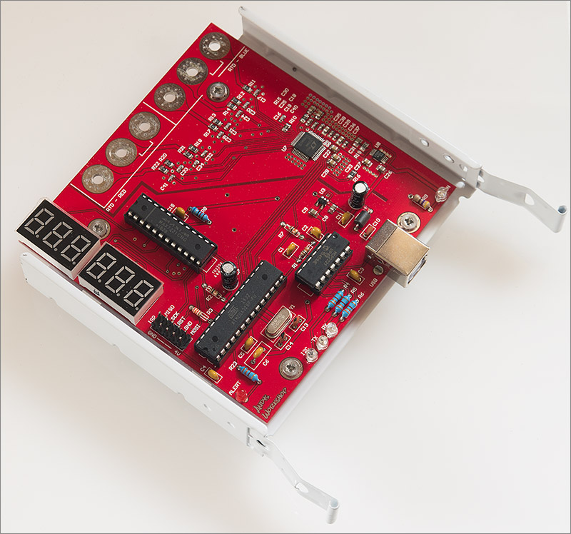
It’s looking nice but does it work? I needed to spend some time writing the firmware.
Testing
I was off to a flying start thanks to the existing firmware for the relays and triacs board, the sample code generated by the LTC2986 application and my existing driver code for the MAX7221. The firmware is designed to poll the two sensors and display their readings at 1Hz intervals. I also implemented a suite of commands to be executed over the serial bus that provide the following functionality:
- Retrieve sensor readings.
- Set or retrieve calibration offsets for each sensor.
- Set or retrieve calibration dates for each sensor.
- Turn on, off or flash the red alarm LED.
- Enable the red, blue or both on-board displays.
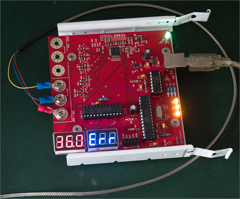
Now all I need to do some testing is a PT100 RTD probe. At this point I wasn’t keen on the idea of paying the relatively high price for a probe from a reputable source. I just wanted to know if my board worked so I bought a couple of cheap probes from ebay. This is the first one that I bought. It claims to be stainless steel.
Stainless steel 3-wire probe from ebay
Before attaching it to the board I used my Keysight U3402A 5½ digit bench meter to take some resistance measurements. After nulling out the test leads I measured the resistance across the two blue terminals. This would give me the lead resistance.
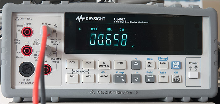
The reading was jumping around a bit due to the contact I was making between the Keysight probes and the spade terminals. I’ll use 658mΩ for this test but I could be off by a couple of hundred milliohms. Now I took a reading across the PT100 element itself.
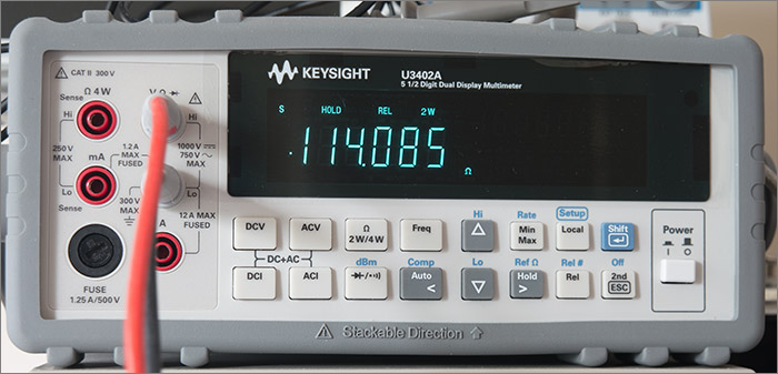
Subtracting the lead resistance gives me a value of 113.427. A resistance-to-temperature lookup table is available online for PT100 probes and I used that to get the temperature.
Hmmm. This probe is off by a mile. The ambient temperature is a comfortable 22°C in this room and the probe is reading a positively scorching 35°C. OK, fine, you pay peanuts and you get peanuts. Fixed offsets can be calibrated out but my concern is whether this probe is actually platinum at all and whether it would change resistance on the correct PT100 scale.
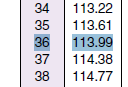
Anyway, I bought it to test the board and I can certainly do that so I hooked it up and switched on. Unfortunately I did grab the probe briefly by its business end while attaching it to the board so it might have heated up slightly while I set up the test.
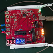
LED readouts are too intense to photograph well
That was a relief. My board reads a value that’s close enough to the lookup table to be my measurement error that was at fault. I sat there watching it for a few minutes, as you do, just to make sure that it was stable. It was. I swapped over to the blue channel and it read the same. Both channels were working.
The unused channel displays ‘Err’ as an indication that it can’t read a value, in this case because there’s no probe attached. More detailed information about the type of error is provided by the firmware serial commands.
I also bought a pair of even cheaper probes from ebay at the same time, just £2.89 gets you one of these.
Is it really possible to get an accurate PT100 probe for under three quid? Well no, actually. I won’t bore you with the photos and measurements again but suffice to say that the two probes I bought didn’t even agree with each other. One was off by 4.7°C and the other was off by a much more respectable 0.3°C.
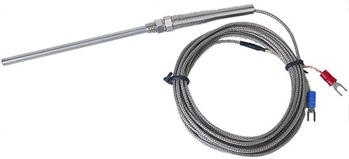
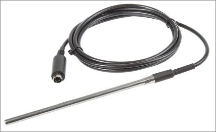
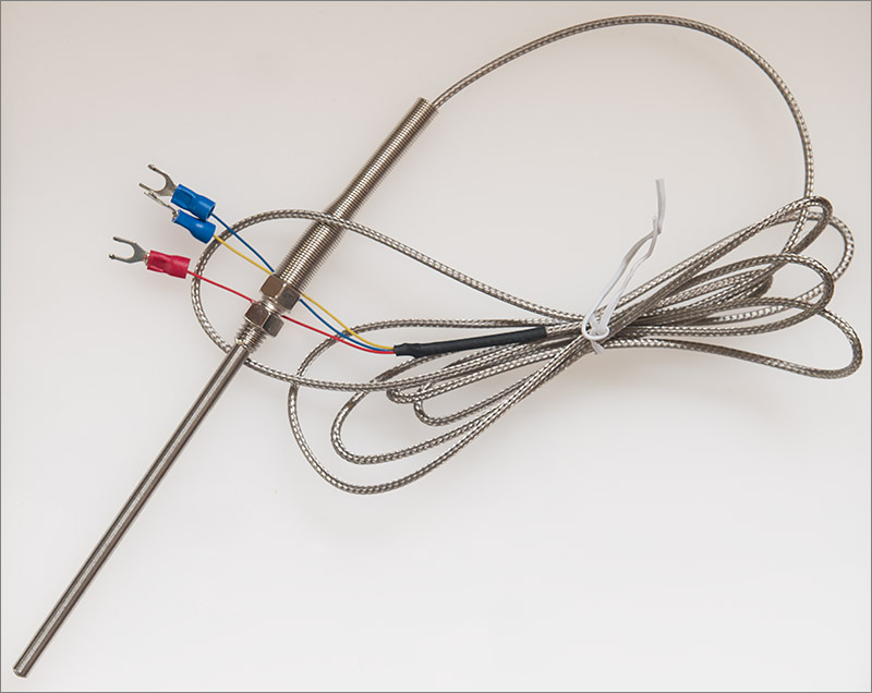
At this point you might be wondering how I know what the true temperature is. The answer is that I have one of these handheld type-T thermocouple probes.
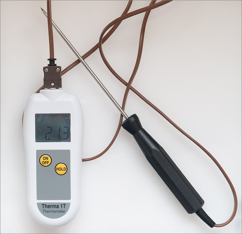
This was calibrated by the manufacturer less than a year ago so it should still be close to the true value. This is the probe that I currently use for all my home brewing measurements and it’s what I’m going to use to set the calibration offsets for these dodgy ebay PT100 probes.
The firmware
The firmware source code can be found here on github. If you don’t want to compile it yourself then you can just download the .hex file from the bin directory and flash it directly to your ATMega328P.
Self-build
If you do want to compile it yourself then the relevant source is in the firmware/rtd directory. Clone the repo, change to the source directory and execute the scons command to compile it. I’ve tested this with the old avr-gcc 4.9.2 and the very recent 7.2.0 release and both work fine.
Here’s the example output when building with 7.2.0:
$ scons
scons: Reading SConscript files ...
scons: done reading SConscript files.
scons: Building targets ...
avr-g++ -o AlarmFlasher.o -c -mmcu=atmega328p -Os -g -DF_CPU=8000000 -DBOARD_SERIAL=2429286624 -std=c++1y -Wall -Werror -Wextra -pedantic-errors -fno-rtti -mcall-prologues -ffunction-sections -fdata-sections -fno-exceptions AlarmFlasher.cpp
avr-g++ -o Max7221.o -c -mmcu=atmega328p -Os -g -DF_CPU=8000000 -DBOARD_SERIAL=2429286624 -std=c++1y -Wall -Werror -Wextra -pedantic-errors -fno-rtti -mcall-prologues -ffunction-sections -fdata-sections -fno-exceptions Max7221.cpp
avr-g++ -o MillisecondTimer.o -c -mmcu=atmega328p -Os -g -DF_CPU=8000000 -DBOARD_SERIAL=2429286624 -std=c++1y -Wall -Werror -Wextra -pedantic-errors -fno-rtti -mcall-prologues -ffunction-sections -fdata-sections -fno-exceptions MillisecondTimer.cpp
avr-g++ -o ProgStrings.o -c -mmcu=atmega328p -Os -g -DF_CPU=8000000 -DBOARD_SERIAL=2429286624 -std=c++1y -Wall -Werror -Wextra -pedantic-errors -fno-rtti -mcall-prologues -ffunction-sections -fdata-sections -fno-exceptions ProgStrings.cpp
avr-g++ -o Program.o -c -mmcu=atmega328p -Os -g -DF_CPU=8000000 -DBOARD_SERIAL=2429286624 -std=c++1y -Wall -Werror -Wextra -pedantic-errors -fno-rtti -mcall-prologues -ffunction-sections -fdata-sections -fno-exceptions Program.cpp
avr-g++ -o Uart.o -c -mmcu=atmega328p -Os -g -DF_CPU=8000000 -DBOARD_SERIAL=2429286624 -std=c++1y -Wall -Werror -Wextra -pedantic-errors -fno-rtti -mcall-prologues -ffunction-sections -fdata-sections -fno-exceptions Uart.cpp
avr-g++ -o brewery-rtd-v1.elf -Wl,-Map,brewery-rtd-v1.map -mrelax -Wl,-u,vfprintf -lprintf_flt -lm -Wl,--gc-sections -mmcu=atmega328p AlarmFlasher.o Max7221.o MillisecondTimer.o ProgStrings.o Program.o Uart.o
avr-objcopy -j .text -j .data -O ihex brewery-rtd-v1.elf brewery-rtd-v1.hex
Install file: "brewery-rtd-v1.hex" as "bin/brewery-rtd-v1.hex"
avr-objdump -S brewery-rtd-v1.elf > brewery-rtd-v1.lst
avr-size brewery-rtd-v1.elf | tee brewery-rtd-v1.siz
   text    data     bss     dec     hex filename
   8850     226     126    9202    23f2 brewery-rtd-v1.elf
scons: done building targets.
If you’d like to flash the .hex file directly to the board using a USBASP programmer then the command is scons upload.
Serial commands
Commands are entered over the USB virtual serial port at 9600 baud. Each command is a single line with optional parameters. An affirmative response is also a single line and is always a valid JSON document to make for easy parsing by the host PC controller.
At the time of writing the following commands are implemented.
| Command | Parameters | Description |
|---|---|---|
| ID | Return the board identifier string. | |
| CAPS | Return the board capabilities. | |
| VER | Return the version numbers. | |
| COPY | Return a copyright statement. | |
| UPTIME | Return the uptime in milliseconds. | |
| READINGS | Return the last temperature readings. | |
| RCAL/BCAL | Return the red/blue calibration offset. | |
| RCAL/BCAL | decimal number | Set the red/blue calibration value. |
| RCALDATE/BCALDATE | Return the red/blue calibration date. | |
| RCALDATE/BCALDATE | 32-bit positive integer | Set the red/blue calibration date as a Unix time_t value. |
| SERIAL | Return the unique serial number generated for this board instance. | |
| ALARM | ON/OFF/FLASH | Change the state of the red alarm LED. |
| DISPLAYS | RED/BLUE/BOTH/NONE | Change which of the 7-segment LED displays to show. Temperature readings are unaffected. |
The serial number returned by the SERIAL command is generated when you first run the scons command and is stored in the serialnumber.txt file. The purpose of this number is to facilitate multiple boards of the same type being used in the same PC. The serial number differentiates them.
I don’t know whether I’ll ever do that but the facility is there if I do. All I need to remember to do is regenerate the serialnumber.txt file when I program a second board of the same type.
Here’s an example interaction with the board using the sendcommand utility that you can find in the bin subdirectory.
$ ./sendcommand /dev/Andy0 READINGS
{"red":{"value":"21.597851","code":"1"},"blue":{"value":"21.554688","code":"1"}}
If the readings are valid then code will be 1. Any other value indicates an error. The error code can be decoded by referring to Table 35. RTD Fault Reporting in the LTC2986 datasheet.
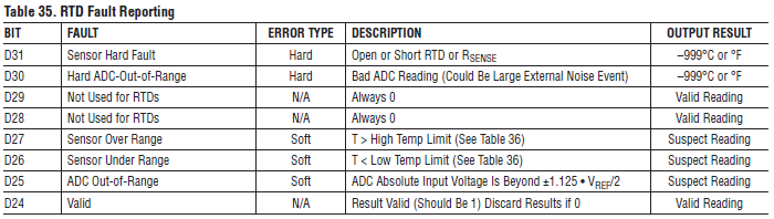
Where it gives a bit position, shift right by 24. So D24 is actually D0.
A good quality probe
Now I’m happy with my board it’s time to stop fooling around with random ebay probes of suspect quality and get hold of a decent one. Here’s the one that I bought.
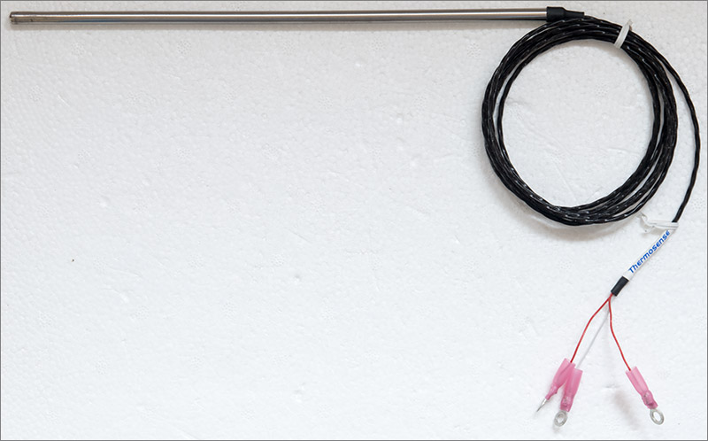
It’s from a company called Thermosense in the UK. It’s stainless steel, 6mm in diameter and 250mm long with a 2 metre lead. I had to crimp on my own loop connectors at the end because it came with a bare-wire termination.
I knew this one was going to be good because it’s used by my professional brewer relative in his automated setup and best of all it was only £22 delivered. I connected it up and sure enough without any calibration at all it was just a tenth or two off my Therma-1T, near enough for me.
I only need one probe at the moment but what I plan to do is to run the cheap ebay stainless one calibrated and side-by-side with the good one from Thermosense. I’ll watch over time to see if the ebay probe responds throughout the range the same as the Thermosense probe and if it does then then there’s no reason to not use the ebay probes if you can calibrate them yourself.
Video
I made a YouTube video showing the board in operation. You can watch it here using the embedded video but much better quality can be had by visiting YouTube and watching it there.
Build your own
If you’d like to build your own board then all the gerbers and firmware are freely available.
Get the gerbers here.
Get the firmware from github here.
Blank boards for sale
I’ve got some spare boards remaining from the batch of ten in my original order. If you’d prefer to buy one rather than have your own set manufactured then you can use the PayPal form below to make an order.
Next time…
Another successful project comes to a conclusion and I’m one big step forward in my goal of producing an automated, PC-based process controller. In fact, except for some physical PC case modifications all the hardware work is done.
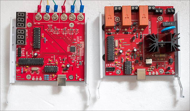
The sensors and the switching boards
The next thing I need to do is move ‘up the stack’ and create the PC controller software that interacts with the hardware. That’s going to be a spring-boot java application distributed in a docker image for easy installation. More on that one in the next article in this series, coming to this blog soon!
If you’d like to leave a comment then you can do so down below in the comments section or if you’d like to add to the discussion over in the forum then please also feel free.