Tags
Related Posts
Share This


Project Difficulty

Recent Posts
Process automation: relays and triacs
In my previous article I discussed how I intended to convert an old PC into a controller that I could use to automate the temperature control required to ferment and conditional beer. If you haven’t already read that introduction then I’d encourage you to do that so you know what it is that I’m trying to achieve.
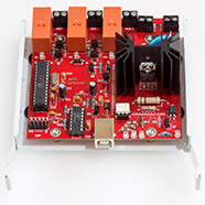
This article will give full details of the first board that I’ve built, designed to fit inside the PC and control relays and triacs.
Design
The heaters, fridge and fans that control the temperature in my brew fridge need to be switched on and off and that’s what this board is designed to achieve.
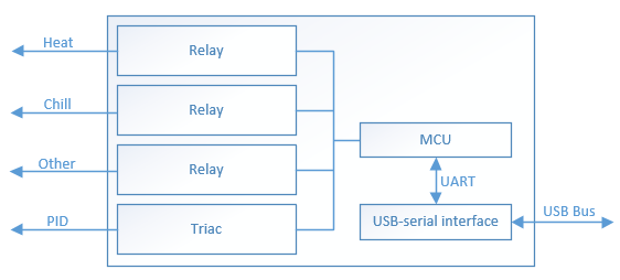
As you can see from the diagram the main features of the board are:
- Three relays for basic on/off switching. To solve one of the issues with the STC-1000 controller I will use 16A, name brand relays for maximum reliability.
- A triac. This will give me the ability to do phase-angle ‘dimming’ control and will be used for proportional heater or fan control.
- USB connectivity to the host PC via a USB-to-UART IC.
I expect that many of my readers will want to build this board so I’ll design it to be all through-hole using easy to find components so that you can build it with just a basic soldering iron. Fancy reflow ovens (much as I love mine) and hot air guns will be not required for this build!
With the design criteria in mind I set about producing a schematic for the board.
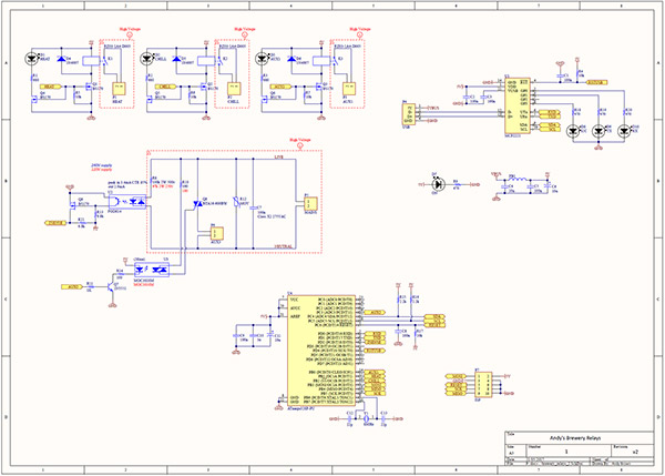
Click on the thumbnail to download a PDF
Let’s do a quick overview of the various functional blocks within the schematic.
Relays
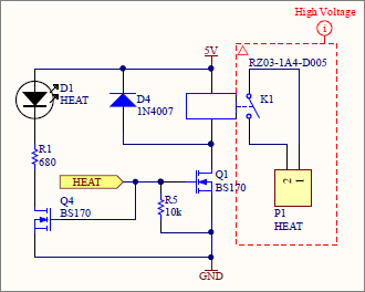
The relay block is repeated three times in the schematic, labelled Heat, Chill and AUX1. There’s no reason why they should actually be controlling heat and chill but I preferred those labels to the more boring 1, 2, 3 etc.
The relays are the RZ03-1A4-D005 by TE Connectivity. They’re 16A rated with a 5V coil and a rated contact voltage of 250VAC. These will be more than enough for my requirements and should last for many years.
The microcontroller activates the relay by driving the base of the MOSFET Q1 and as long as the base is held high then the relay will remain switched on. This is known as a non-latching relay and it’s important because we want the system to fail-safe, i.e. off, if there’s a system power failure. R5 pulls the MOSFET base down to ground so that the relay remains off during system power-up when the driving signal is in an indeterminate state.
The signal that drives Q1 also drives Q4 to light an indicator LED that will give a visual indication that the relay is on. With the board inside the case I won’t be able to see this but if you’re building it and have one of those cases with a window on the side then you will see it.
D4 is the protection diode and I’m using the 1N4007 because I’ve got lots of them. In practice any of the 1N400x series will work fine. P1 is a two-terminal connection block that will have an appropriate current rating for this board.
I’ve created a net class for the high-voltage parts of the circuit so that when it comes to the PCB layout I can apply design rules such as minimum trace width and clearance to just those parts of the circuit.
The triac and its controller
The triac gives me the ability to do phase-angle ‘dimming’ control of the mains AC sine wave. If you’re coming to this from a microcontroller background where the supply is both DC and low voltage then you’re probably familiar with the common Pulse Width Modulation (PWM) technique that’s used to give the appearance of dimming, often with LEDs, by rapidly switching the DC supply on and off and relying on our human persistence of vision to give the perception of a constant light level.
This works well for DC supplies but can the same technique be applied to the mains AC supply where the signal is a dangerously high voltage and a sine wave? The straight answer is that no you can’t, but you can achieve the same result with what we call Phase Angle Control.
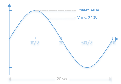
Here’s what the mains supply sine wave looks like in the UK where I live. We have a nominal supply voltage of 240V RMS at a frequency of 50Hz although the actual RMS voltage delivered to the house will vary depending on all sorts of things such as your distance from the local substation and the demand in the area at the time. As I write this on a Sunday lunchtime I’m seeing 238V and I’ve seen it up to the full 240V at other times.
To give the appearance of dimming a load we rely on the same basic rapid on/off switching of the supply as we do with the PWM technique but we must observe an additional constraint. We cannot choose any frequency we like, instead we must use the same frequency as the mains supply and we must stay in sync with it. In the UK that means we’ll be operating our dimmer at 100Hz (once for the positive half of the 50Hz signal and again for the negative half).
So, we need a technique for detecting when the sine wave passes through the zero point on the X-axis so that we can stay in sync with it and we also need a device that can rapidly switch a load on and off regardless of the polarity of the signal.
Let’s deal with the switching device first. The most commonly used component is the triac because it’s small, cheap and can be made to handle large currents and voltages. A triac is a type of bi-directional thyristor that only conducts when triggered by a current at its gate.
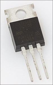
Triac’s have three terminals. Two of them are intuitively labelled MT1 and MT2 for ‘Main Terminal’ one and two. Your load current flows between these two terminals, but only when the triac has been triggered by a current at its gate. In traditional dimming circuits where the mains is the only supply available a component called a diac is often used to drive the gate of a triac.
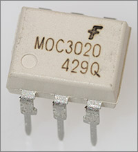
These days with low voltage DC logic circuits so popular ‘logic level’ triacs have become available that are easily triggered by a low gate current and they are often accompanied by a dedicated triac optocoupler to provide isolation between the low and high voltage sides. The Fairchild MOC30x0 series is very popular and that’s the one I’ll be using in my circuit.
Once activated by a pulse of sufficient duration and magnitude at its gate then a triac will latch ‘on’ until the zero crossing current point when it will attempt to turn itself off.
Triggering in a Triac is explained by dividing up the relative polarities of the 3 terminals into quadrants. You can read about these in the Wiki article so I won’t go into it again in depth here. One important takeaway from the Wiki article is the note about three quadrant, or snubberless triacs.
When driving loads with a significant reactive component the triac is particularly vulnerable to false triggering in quadrant four. By disabling triggering in this quadrant this vulnerability is reduced so much that the typical RC snubber circuit that you often see may not be required. I usually drive loads that are almost purely resistive such as heating and lighting but I still exclusively use 3Q triacs because they cost the same as 4Q triacs and I don’t need the RC snubber components.
Now we know how we’re going to turn the mains on and off we need to examine when we’re going to do it.
Zero crossing detection
There are countless ways to do this. Sometimes you don’t even need to design a specific sub-circuit for it because it will be naturally available at a particular node in your design, as was the case in my reflow oven power-supply circuit. Some designs are potentially unsafe because they don’t isolate the mains voltage from the low voltage detection circuit.
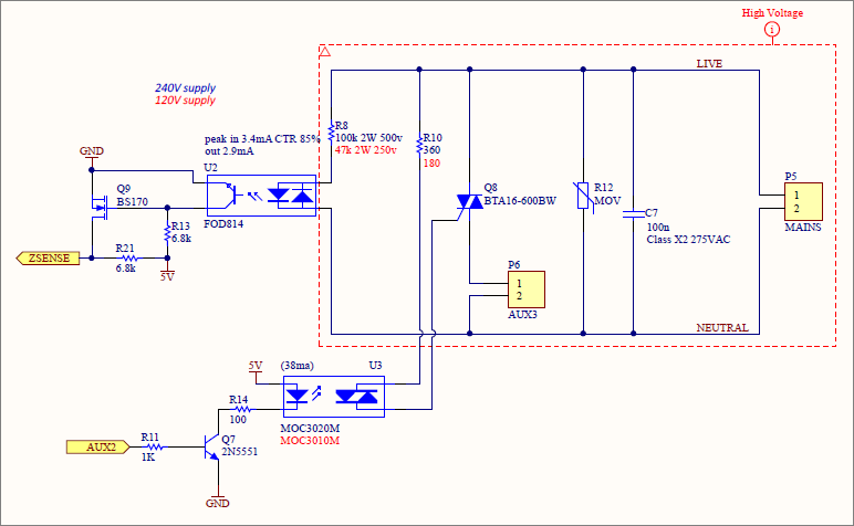
The design I’ve chosen is both safe and cheap but does come at the cost of about 0.5W of power consumption. It’s safe because it optically isolates the mains from the low voltage side and it’s cheap because it uses just three resistors, an AC optocoupler and a MOSFET.
This circuit will provide a falling edge pulse at the zero current crossing point. R8 limits the current flowing through the optocoupler to the smallest value that we can get away with so that the power dissipated inside R8 is minimised. The optocoupler provides safe isolation between the mains and the low voltage side of the circuit.
When current is available from the mains to light the LEDs inside the optocoupler then the opposing phototransistor will conduct current from 5V through R2 and so to ground. A microcontroller input pin attached to the ZSENSE point will sense 5V through the resistor R21 and read a high level. It doesn’t matter whether the load has inductive or reactive components because the LEDs in the optocoupler are lit by current, not voltage.
At or very near the point of the zero crossing the phototransistor will stop conducting. The 5V voltage will then activate the gate of the MOSFET causing current to flow through R21 and across the MOSFET to ground. Our microcontroller will now sense a low level and we have a falling edge of a logic signal that we can use to trigger an interrupt and start our work.
The values for R21 and R13 are important to the accuracy of the zero crossing detection and were derived empirically with the aid of a test circuit and an oscilloscope.
Now we’re in full possession of all the pre-requisites for controlling the mains supply we can illustrate what we’re going to do with a simple flow chart.
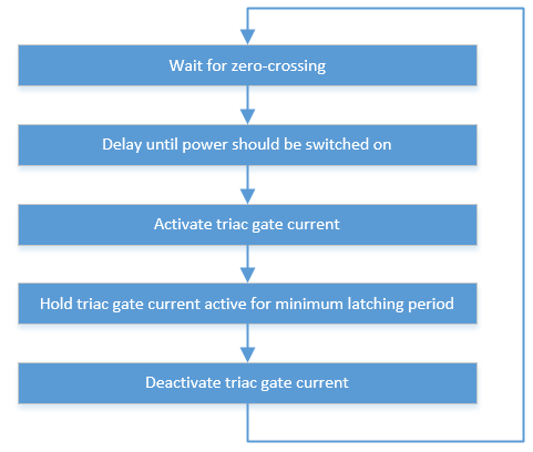
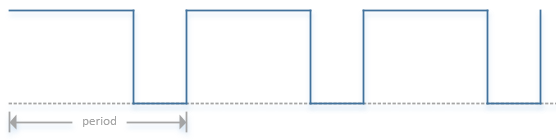
If we put that into action then our ‘dimmed’ mains signal might look like this.
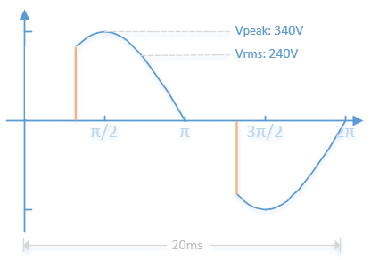
The orange lines indicate where we activate the triac and switch on the load. The triac automatically switches off at the next zero crossing and we start our timing cycle again. The chopped waveform is sufficent to give the appearance of dimming in loads that can support it.
To complete the design R12 is a MOV to protect the triac from voltage spikes and C7 is for interference suppression.
The microcontroller
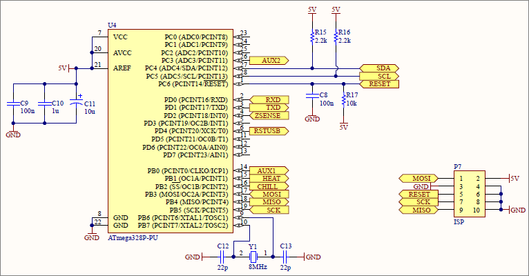
Yes it’s the venerable old ATMega328P as popularised by the Arduino and its clone army, chosen for this design because its wide availability, easy programming model, through-hole packaging and 5V voltage compatibility. I’ve opted to include an 8MHz crystal on the board in case I decide that the firmware should have the ability to run a timed program over the course of several days even if the main host computer has crashed. External crystal’s are just about accurate enough to do that whereas the internal RC oscillator is not.
The USB controller
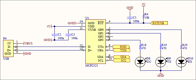
There are many USB-to-UART bridge chips around but when my design criteria for through-hole devices is taken into account that list drops down to one, the MCP2221 from Microchip. It’s trivial to use in that you just hook one side up to your MCU, the other side to the USB port and you can immediately start talking to it at 9600 baud. Rumour has it that it’s actually a hard-wired PIC inside that package.
I’ve connected up the I2C bus even though I probably won’t use it and I’ve also added the three LEDs that indicate activity. These will be normally-on, flashing briefly off when there’s activity.
Now we’ve seen the design, it’s time to move on to the PCB layout.
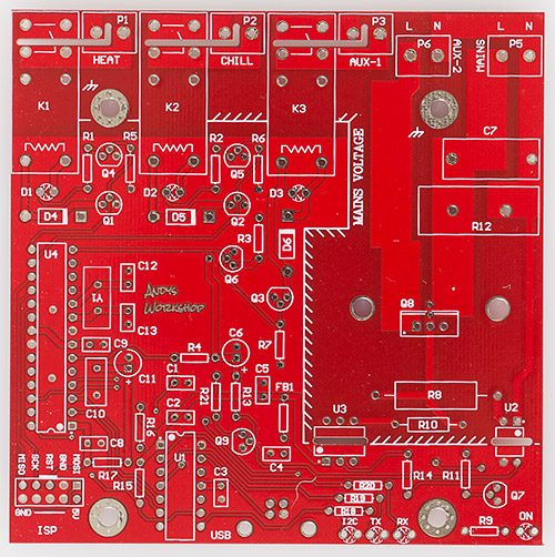
PCB Design
There are two main constraints that I need to work with when laying out the board. Firstly, the mounting holes must fit the footprint of a 2.5″ hard drive so that the board can be mounted in a PC drive bay. Secondly the overall size of the board should fit within the 10x10cm format that’s so cheap to have manufactured in China.
With the board outline defined and the screw holes placed I then positioned the relays and the triac so that their associated terminal blocks would all face in one direction off the board. The USB ‘B’ connector was placed at the other end of the board so that we have data coming in at one side and the high voltage section all at the other side.
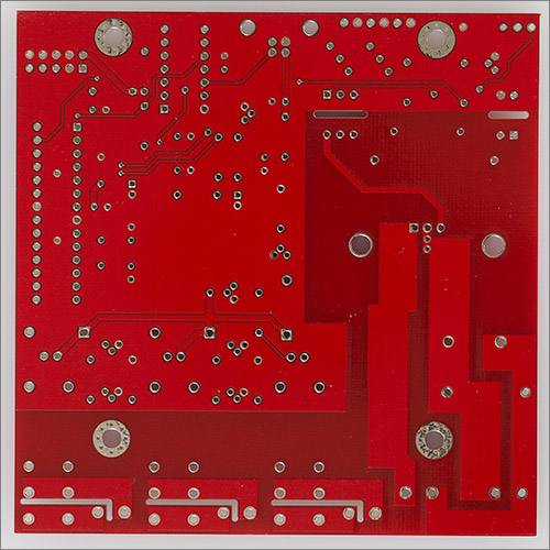
Now it was simply a matter of placing all the other components in as much of a logical place as possible and routing them all up. The board layout is finalised with top and bottom ground pours in the low-voltage areas and teardrop connections to all the pads for better connection integrity.
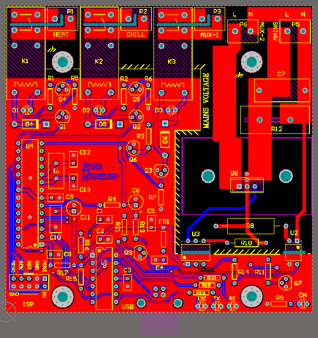
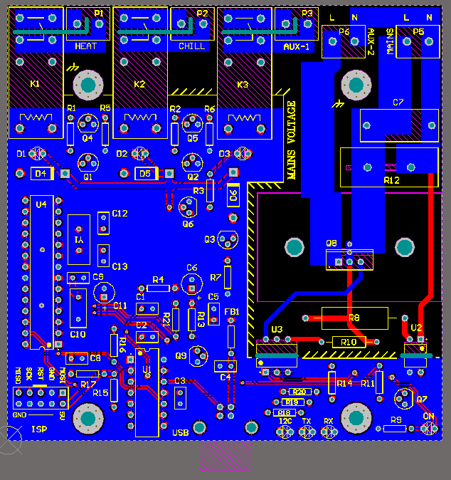
I added a silkscreen border and some text to make it clear where the high voltage areas are located on this board.
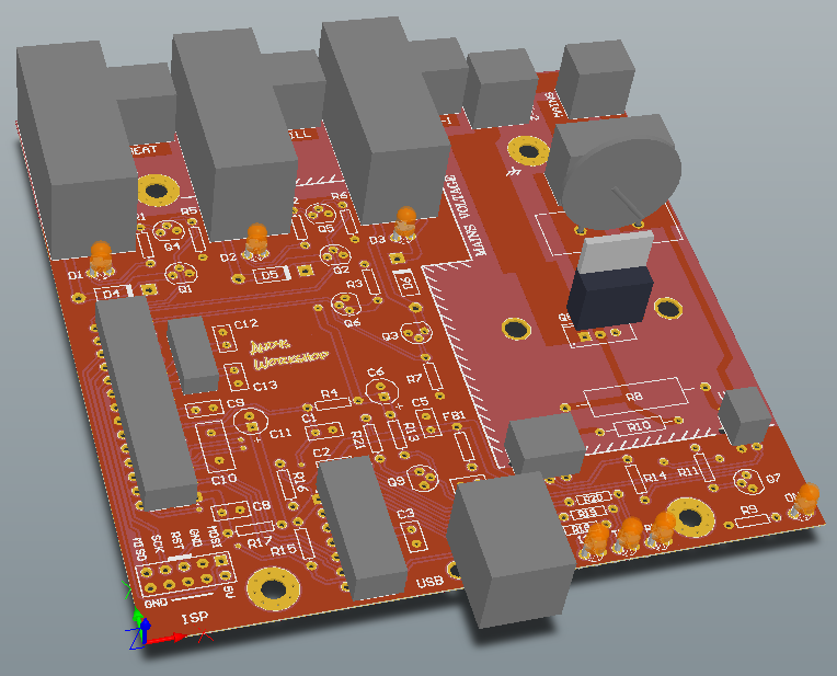
Another useful step in the verification process is to view the board in 3D mode where I can check the heights of all the components that I have models for and easily see common errors such as silkscreen overlapping pads.
All of the parts are available at Farnell so I put in an order for those and also for 10 copies of the PCB from Seeed Studio in China since they were having a crazy offer of US$4.90 for 10 before postage.
Bill of Materials
Here’s the bill of materials for this design showing component values for a 220-240V mains supply. Refer to the schematic for suggested values for a 120V supply.
| Designator | Value | Quantity | Description | Footprint | Farnell code | Notes |
|---|---|---|---|---|---|---|
| C1, C2, C3, C5, C8, C9 | 100n | 6 | Ceramic capacitor | 2.54mm | 2309020 | |
| C4 | 10n | 1 | Ceramic capacitor | 2.54mm | 2309024 | |
| C6, C11 | 10µ | 2 | Electrolytic capacitor | 5x11mm | 1902913 | |
| C7 | 100n | 1 | Panasonic ECQU2A104KLA X2 Film Capacitor | 1673308 | ||
| C10 | 1µ | 1 | Ceramic capacitor | 5.08mm | 2112910 | [1] |
| C12, C13 | 22p | 2 | Ceramic capacitor | 2.54mm | 1100369 | |
| D1, D2, D3 | White | 3 | LED | 3mm | [3] | |
| D4, D5, D6 | 1N4007 | 3 | Diode | DO-41 | 2317417 | [2] |
| D7 | Green | 1 | LED | 3mm | [3] | |
| D8, D9, D10 | Amber | 3 | LED | 3mm | [3] | |
| FB1 | BLM18PG221SN1D | 1 | Ferrite bead | AXIAL-0.3 | 2292304 | |
| K1, K2, K3 | RZ03-1A4-D005 | 3 | Single-Pole Single-Throw Relay | 2325624 | ||
| P1, P2, P3, P5, P6 | PM5.08/2/90 | 3 | WEIDMULLER PM5.08/2/90 | PCB terminal block - 5.08 | 1131855 | |
| P4 | USB B | 1 | USB B RECEPTACLE | 1177885 | ||
| P7 | 2x5 header | 1 | ISP connector | 2.54mm | [4] | |
| Q1, Q2, Q3, Q4, Q5, Q6, Q9 | BS170 | 7 | N-Channel MOSFET | TO-92 | 1017687 | |
| Q7 | 2N5551 | 1 | NPN Bipolar Transistor | TO-92 | 9846751 | |
| Q8 | BTA16-600BW | 1 | Triac | TO-220 | 1175636 | |
| R1, R2, R3 | 680 | 3 | Resistor | AXIAL-0.3 | 2329545 | |
| R4, R5, R6, R7, R17 | 10k | 5 | Resistor | AXIAL-0.3 | 2329474 | |
| R8 | 100k 2W 500v | 1 | Resistor | AXIAL-0.9 | 2329558 | |
| R9, R18, R19, R20 | 470 | 4 | Resistor | AXIAL-0.3 | 2329531 | |
| R10 | 360 | 1 | Resistor | AXIAL-0.5 | 2329779 | |
| R11 | 1k | 1 | Resistor | AXIAL-0.3 | 2329486 | |
| R12 | 275VRMS | 1 | MOV | Varistor 20D series | 1856919 | |
| R13, R21 | 6.8k | 2 | Resistor | AXIAL-0.3 | 1700247 | |
| R14 | 100 | 1 | Resistor | AXIAL-0.3 | 2329473 | |
| R15, R16 | 2.2k | 2 | Resistor | AXIAL-0.3 | 2329584 | |
| U1 | MCP2221-I/P | 1 | Microchip USB-Serial | DIP-14 | 2434892 | |
| U2 | FOD814A | 1 | Optocoupler | DIP-4 | 2322510 | |
| U3 | MOC3020M | 1 | Opto-Triac | DIP-6 | 1471017 | |
| U4 | ATMega328p | 1 | 8-bit AVR Microcontroller | DIP-28 | 1715487 | |
| Y1 | 8MHz | 1 | Crystal Oscillator | HC49 thru hole | 2063945 | |
| Ohmite FA-T220-38E | 1 | Triac heatsink | 2097690 |
Notes
Some of the components have note numbers against them. The following numbered paragraphs correspond to a numbered note in the bill of materials table.
- 2.54mm parts can also be used if you carefully bend the leads outwards to fit the wider 5.08mm pitch.
- Any of the 1N400x series will be fine. They all cost about the same so I tend to keep a stock of the biggest one, the 1N4007 around.
- Any colour of 3mm LED will work and they’re cheapest on ebay.
- These 2.54mm headers are cheapest on ebay.
Assembly
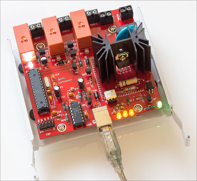
The boards arrived in about 3 weeks and they look very good. It’s just ridiculous how cheaply these can be produced these days.
Assembling a purely through-hole board is as simple as sitting down with my soldering iron, a pair of snips and just getting on with it. You can make life easier for yourself by doing the components in ascending height order. That means starting with the resistors and moving up through the diodes, capacitors etc.
I choose to use sockets for all my DIP ICs though you don’t have to if you’re confident that your design is going to work first time.
An important thing to note is that you must solder the triac so that when the heatsink is attached there is at least a millimetre or two of air clearance between the heatsink and the board because there are high voltage traces running under the heatsink and you wouldn’t want to be depending on the soldermask and the heatsink’s own coating for insulation.
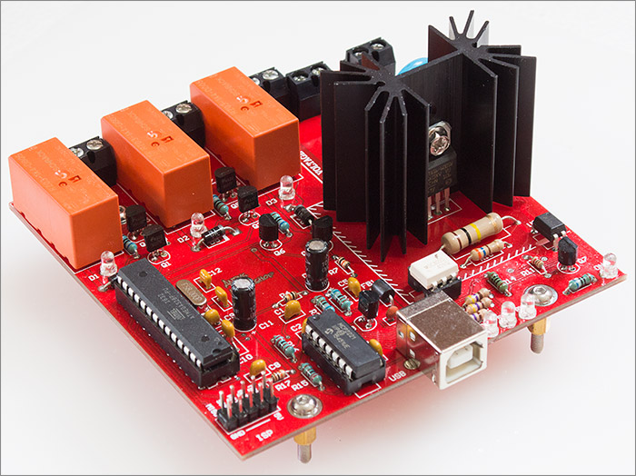
Looking good with all those chunky through-hole parts on board. Here’s another shot showing it mounted on a hard disk caddy.
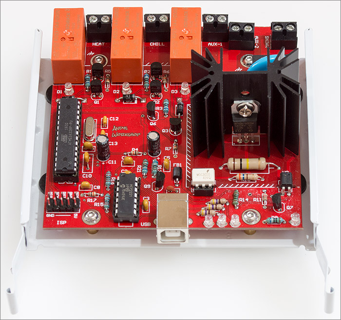
As you can see it fits nicely into the footprint of the hard disk caddy where the screw holes in the board mate up with the footprint for a 2.5″ hard disk.
Testing
Firstly I need to plug it in and see what happens. The MCP2221 should be completely autonomous and enumerate as a USB device without any firmware even being flashed on to the ATmega328p. Since the target operating system for the computer hosting this device is Linux I’ll be doing all my testing on a Ubuntu VM running under the free VMware player. My main PC runs Windows 10 as the host OS because nearly all the applications that I use on a daily basis are for Windows but since I have 48Gb of RAM it’s no problem at all to have at least one Linux server VM running for those processes that just run better on Linux.
I plugged it in. There was a chime from the PC, VMware found the device and I told it to send it to the guest OS. Time to see if it’s there.
$ ls -l /dev/usb* /dev/ttyACM*
crw-rw-rw- 1 andy dialout 166, 0 May 27 14:28 /dev/ttyACM0

/dev/usb:
total 0
crw------- 1 root root 180, 0 May 27 14:28 hiddev0
Cool, looks like I have new CDC and HID devices. Let’s get some info on it.
$ lsusb
Bus 001 Device 001: ID 1d6b:0002 Linux Foundation 2.0 root hub
Bus 002 Device 004: ID 04d8:00dd Microchip Technology, Inc.
Bus 002 Device 003: ID 0e0f:0002 VMware, Inc. Virtual USB Hub
Bus 002 Device 002: ID 0e0f:0003 VMware, Inc. Virtual Mouse
Bus 002 Device 001: ID 1d6b:0001 Linux Foundation 1.1 root hub
There it is on the second row. All the descriptors retrieved during device enumeration are retrievable by passing the -v flag to lsusb
$ lsusb -vd 04d8:00dd

Bus 002 Device 004: ID 04d8:00dd Microchip Technology, Inc.
Couldn't open device, some information will be missing
Device Descriptor:
  bLength                18
  bDescriptorType         1
  bcdUSB               2.00
  bDeviceClass          239 Miscellaneous Device
  bDeviceSubClass         2 ?
  bDeviceProtocol         1 Interface Association
  bMaxPacketSize0         8
  idVendor           0x04d8 Microchip Technology, Inc.
  idProduct          0x00dd
  bcdDevice            1.00
  iManufacturer           1
  iProduct                2
  iSerial                 0
  bNumConfigurations      1
  Configuration Descriptor:
    bLength                 9
    bDescriptorType         2
    wTotalLength          107
    bNumInterfaces          3
    bConfigurationValue     1
    iConfiguration          0
    bmAttributes         0x80
      (Bus Powered)
    MaxPower              100mA
    Interface Association:
      bLength                 8
      bDescriptorType        11
      bFirstInterface         0
      bInterfaceCount         2
      bFunctionClass          2 Communications
      bFunctionSubClass       2 Abstract (modem)
      bFunctionProtocol       1 AT-commands (v.25ter)
      iFunction               0
    Interface Descriptor:
      bLength                 9
      bDescriptorType         4
      bInterfaceNumber        0
      bAlternateSetting       0
      bNumEndpoints           1
      bInterfaceClass         2 Communications
      bInterfaceSubClass      2 Abstract (modem)
      bInterfaceProtocol      1 AT-commands (v.25ter)
      iInterface              0
      CDC Header:
        bcdCDC               1.10
      CDC ACM:
        bmCapabilities       0x02
          line coding and serial state
      CDC Union:
        bMasterInterface        0
        bSlaveInterface         1
      CDC Call Management:
        bmCapabilities       0x00
        bDataInterface          1
      Endpoint Descriptor:
        bLength                 7
        bDescriptorType         5
        bEndpointAddress     0x81  EP 1 IN
        bmAttributes            3
          Transfer Type            Interrupt
          Synch Type               None
          Usage Type               Data
        wMaxPacketSize     0x0008  1x 8 bytes
        bInterval               2
    Interface Descriptor:
      bLength                 9
      bDescriptorType         4
      bInterfaceNumber        1
      bAlternateSetting       0
      bNumEndpoints           2
      bInterfaceClass        10 CDC Data
      bInterfaceSubClass      0 Unused
      bInterfaceProtocol      0
      iInterface              0
      Endpoint Descriptor:
        bLength                 7
        bDescriptorType         5
        bEndpointAddress     0x02  EP 2 OUT
        bmAttributes            2
          Transfer Type            Bulk
          Synch Type               None
          Usage Type               Data
        wMaxPacketSize     0x0010  1x 16 bytes
        bInterval               0
      Endpoint Descriptor:
        bLength                 7
        bDescriptorType         5
        bEndpointAddress     0x82  EP 2 IN
        bmAttributes            2
          Transfer Type            Bulk
          Synch Type               None
          Usage Type               Data
        wMaxPacketSize     0x0010  1x 16 bytes
        bInterval               0
    Interface Descriptor:
      bLength                 9
      bDescriptorType         4
      bInterfaceNumber        2
      bAlternateSetting       0
      bNumEndpoints           2
      bInterfaceClass         3 Human Interface Device
      bInterfaceSubClass      0 No Subclass
      bInterfaceProtocol      0 None
      iInterface              0
        HID Device Descriptor:
          bLength                 9
          bDescriptorType        33
          bcdHID               1.11
          bCountryCode            0 Not supported
          bNumDescriptors         1
          bDescriptorType        34 Report
          wDescriptorLength      28
         Report Descriptors:
           ** UNAVAILABLE **
      Endpoint Descriptor:
        bLength                 7
        bDescriptorType         5
        bEndpointAddress     0x83  EP 3 IN
        bmAttributes            3
          Transfer Type            Interrupt
          Synch Type               None
          Usage Type               Data
        wMaxPacketSize     0x0040  1x 64 bytes
        bInterval               1
      Endpoint Descriptor:
        bLength                 7
        bDescriptorType         5
        bEndpointAddress     0x03  EP 3 OUT
        bmAttributes            3
          Transfer Type            Interrupt
          Synch Type               None
          Usage Type               Data
        wMaxPacketSize     0x0040  1x 64 bytes
        bInterval               1
Endpoints are visible for the CDC and HID devices in that list. I don’t care about the HID device and will just be addressing the ATMega328p’s UART through the CDC interface at the default speed of 9600 baud.
In its default state Linux will only allow root to talk to a /dev/ttyACM device. I need to change that so my ordinary unprivileged user can use it and thankfully Linux provides a way. Adding the following udev rules file did the trick.
$ cat /etc/usdev/rules.d/20-brewery-controllers.rules
SUBSYSTEM=="tty" ATTRS{manufacturer}=="Microchip Technology Inc." SYMLINK+="Andy%n" MODE="0666", OWNER="andy"
With this in place I’ll get user-accessible symlinks automatically created and removed that point to the real devices.
$ ls -l /dev/Andy*
lrwxrwxrwx 1 root root 7 May 27 14:28 /dev/Andy0 -> ttyACM0
Next I needed to test that the MCU is alive so I connected up my USBASP programmer and read out the fuses using avrdude. I had to do this from Windows because for reasons I never got to the bottom of the USBASP programmer will not with Avrdude when the Linux host is running in a virtual machine. This means that I’m developing in a split-personality system where the MCP2221 is connected to the Linux guest and the USBASP is connected to the Windows host with the systems sharing source code using a VM mount on to the host filesystem. Fun times.
There were no problems. The MCU was up and running so now it’s time for me to create some firmware.
The firmware operates in a simple command/response mode over the UART. You can see the source code here on github. Each command must be terminated by a CRLF pair and the single line response will also be terminated the same way. The accepted command set is:
| Commands | Expected response | Description |
|---|---|---|
| HEAT ON HEAT OFF | OK | Turns the HEAT relay on or off |
| CHILL ON CHILL OFF | OK | Turns the CHILL relay on or off |
| AUX1 ON AUX1 OFF | OK | Turns the AUX1 relay on or off |
| AUX2 <percent> | OK | Sets the AUX2 triac 'dimmer' level to the specified percentage |
| ID | JSON text | Returns the board identifier string as JSON |
| COPY | plain text | Returns a copyright statement valid for this board |
| VER | JSON text | Returns the hardware and firmware versions of the board |
| CAPS | JSON text | Returns the capabilities (number of relays etc) of this board |
| UPTIME | OK:<ms> | Milliseconds |
| VALID heat chill aux1 aux2 | OK | Sets the 'valid mask' of permitted switch combinations |
Most of the commands are obvious in what they do and the reason for some of them returning JSON is so that they can be easily parsed by the linux server process that I will create to manage the communication between the user interface and the hardware.
The VALID command is a safety feature that sets which switches are permitted to be on at the same time, so for example if the user asks for the heater and chiller to be switched on at the same time the firmware will not permit it. The default setting in the firmware is for all the controls to be isolated from each other. That is, no relay or triac may be on at the same time as any of the others. The documentation for how to specify the four parameters can be found in the source code here on github.
If you don’t want to build the firmware from source then you can find a pre-built hex file in the bin directory of the github repo. Building from source requires a local installation of avr-gcc that supports C++11, I used 4.9.2, and also an installation of the scons build system.
To build from source and simultaneously upload using the USBASP programmer the command is:
$ scons mains=50 upload
scons: Reading SConscript files ...
scons: done reading SConscript files.
scons: Building targets ...
avrdude -c usbasp -p m328p -e -U flash:w:brewery-relays.hex

avrdude.exe: warning: cannot set sck period. please check for usbasp firmware update.
avrdude.exe: AVR device initialized and ready to accept instructions

Reading | ################################################## | 100% 0.00s

avrdude.exe: Device signature = 0x1e950f
avrdude.exe: erasing chip
avrdude.exe: warning: cannot set sck period. please check for usbasp firmware update.
avrdude.exe: reading input file "brewery-relays.hex"
avrdude.exe: input file brewery-relays.hex auto detected as Intel Hex
avrdude.exe: writing flash (4196 bytes):

Writing | ################################################## | 100% 2.85s

avrdude.exe: 4196 bytes of flash written
avrdude.exe: verifying flash memory against brewery-relays.hex:
avrdude.exe: load data flash data from input file brewery-relays.hex:
avrdude.exe: input file brewery-relays.hex auto detected as Intel Hex
avrdude.exe: input file brewery-relays.hex contains 4196 bytes
avrdude.exe: reading on-chip flash data:

Reading | ################################################## | 100% 2.16s

avrdude.exe: verifying ...
avrdude.exe: 4196 bytes of flash verified

avrdude.exe done.  Thank you.
If you live in a country where the mains supply is 60Hz then simply change mains=50 to mains=60.
The first time you build, you must also set the fuses so that the MCU uses the external 8MHz crystal. The command for that is:
$ scons mains=50 fuse
Linux offers a range of serial comms programs that I can use for testing. I briefly tried screen, cu and minicom and couldn’t get them to work well in reasonable time because their defaults are set up for real terminals on the ‘other end’. Python came to the rescue with the miniterm utility built in to the PySerial package. Here’s an example of me using it.
$ python -m serial.tools.miniterm /dev/Andy0
--- Miniterm on /dev/Andy0  9600,8,N,1 ---
--- Quit: Ctrl+] | Menu: Ctrl+T | Help: Ctrl+T followed by Ctrl+H ---
"Andy's Workshop Brewery switching controller"␀
{"type":"switching","relays":["HEAT","CHILL","AUX1"],"triacs":["AUX2"]}␀
{"hardware":1,"firmware":1}␀
My firmware does not echo back the characters that you type because it would be pointless in an automated system. You have to take it on trust that the device is actually receiving what you type, or if you stare intently at the middle of the three indicator LEDs then you’ll see it briefly flash off and on again each time you press a key. In the above session I typed id, caps and ver.
Now let’s switch a relay on and see the result. The command to enter is heat on
--- Miniterm on /dev/Andy0  9600,8,N,1 ---
--- Quit: Ctrl+] | Menu: Ctrl+T | Help: Ctrl+T followed by Ctrl+H ---
OK␀
The firmware responded with OK, there was a solid sounding clunk from the relay and the white indicator LED switched on.
The relays have an advertised maximum switching frequency of 360 times per hour when loaded, or once every 10 seconds. The application software that I write will not allow anything like this rate but one should never rely on software to always do the right thing so the firmware is coded to prevent any one relay being switched on twice in a 10s period. If you try, this happens.
--- Miniterm on /dev/Andy0  9600,8,N,1 ---
--- Quit: Ctrl+] | Menu: Ctrl+T | Help: Ctrl+T followed by Ctrl+H ---
ERROR:05:Relay 10s blackout active␀
The other two relays all checked out good so now I need to test the triac before I can call it a day. This isn’t as simple as testing the relays because I’ll need to hook up the mains input and a test load to the AUX2 output. I’ll use a portable worklight for the load. Let’s give it a go.
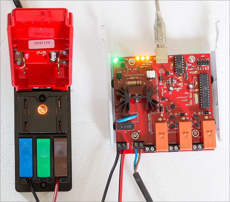
My ‘Quick Test’ box by Cliff Electronics gives me a quick way to hook up the mains supply safely to the board. I tested the triac using the AUX2 <percentage> command with percentage values from 0 to 100 in steps of 10. The light responded correctly which indicated that the mains dimming logic and all the timers associated with that were working as designed.
That’s enough testing for today. I now have a working board and can move on to the next phase of the project which I think will be the RTD temperature sensors board.
Video
I made a YouTube video showing the board in operation. You can watch it here using the embedded video but much better quality can be had by visiting YouTube and watching it there.
Build your own
Although I have a specific use for this board the general concept of an internal PC board that can be used to switch and dim mains loads may have wider appeal. Visit my downloads page to get the Gerber files for this project. You can upload those to one of the cheap online services such as Seeed, ITead, PCBWay and get some copies manufactured for yourself.
You build and use this board at your own risk. Please be extremely careful when handling mains wiring. Never touch any part of the board while the supply is connected and always secure cabling inside a housing in such a way that it cannot move. If in doubt, get a qualified electrician to do it or at least have one review your work.
All the firmware and application source code is here on github.
Blank boards for sale
I’ve got some spare boards remaining from the batch of ten in my original order. If you’d prefer to buy one rather than have your own set manufactured then you can use the PayPal form below to make an order.
Final words
This is the first concrete implementation of a board for my process controller and I’m very happy with the results so far, especially since I have no previous experience with the MCP2221 USB controller and yet it worked first time. I’ll be moving on now to the next stage of the project which will be to build a temperature sensor board based on RTD probes.
If you’d like to leave a comment then you can do so down below in the comments section or if you’d like to add to the discussion over in the forum then please also feel free.