


USB HID device development on the STM32 F042
The STM23 F042 series is ST’s cheapest route into USB device programming for the F0 series of STM32 microcontrollers. In hacker-friendly units of one you can buy an STM32F042F6P6 (48Mhz, 32Kb flash, 6Kb SRAM, TSSOP20) for £1.47 at Farnell today.
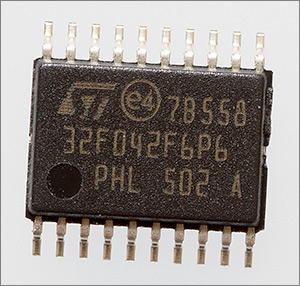
STM32F042 TSSOP20 0.65mm pitch package
If you need more IO pins then there are QFP and QFN (curse them!) packages available but you’re stuck with 32Kb flash and 6Kb SRAM memory limitations. If you need more of those resources then you’ll have to step up to something like the F072 range.
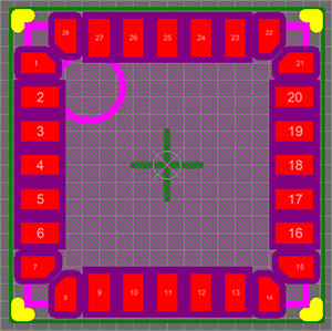
The footprint for ST’s QFN 28 is pictured above. Not an easy one to work with, and not just because of the usual difficulties with seeing what you’re doing and subsequently have done but also because ST have shrunk the size of the corner pads to make the package even smaller. Always use ST’s official PCB footprint for this package and don’t use a generic QFN-28. Better still, save yourself a headache and don’t use a QFN at all!
USB on the STM32F042F6P6
In my last article I presented a simple development board for the F6P6 TSSOP20 variant of the F042 and since then I’ve been using it to develop a USB custom HID device. It all went well and so I thought I’d explain how I did it and hopefully you can pick up some design, implementation and debugging tips for your own project.

My miniature development board
USB
USB is an absolulely maahoosive protocol, definitely the largest that I’ve ever seen and far more than one person can fit in their brain and still have room for anything else. The way to tackle it is to understand the high level design and which of the many sub-protocols is applicable to you and then learn that sub-protocol along with the initial device enumeration stage. If you can do that then you’ll know enough to create a reliable USB device of your own.
The best technical online guide that I’ve found is USB in a nutshell. Calling it a nutshell is a bit of a stretch of the imagination but it is well written and makes a great read if you got some time to spare.
In the rest of this article I’m going to refer to endpoints, descriptors, hosts and devices so if you’re not familiar with these terms then I recommend that you visit the USB in a nutshell pages and brush up on those USB basics.
USB HID
The subprotocol that I’m interested in is the Human Interface Device (HID) protocol. This protocol was intended to support keyboards, mice and joysticks. Basically anything that you can attach that could work by exchanging small interrupt-driven data packets with the host.
The USB implementors forum have a website dedicated to the HID specification and it’s worth a quick look. In particular you should have a copy of the Device Class Definition for HID 1.11 PDF availble here and also the HID Descriptor Tool Windows utility available from the same page. We’ll have a look at that tool later on.
HID descriptors
I mentioned in the previous paragraph that HID devices exchange data with the host using small interrupt-driven data packets. The data that you send in these packets can be structured or free-form. Structured data is formatted in a way that the host understands. For example, there are defined ways of representing key presses and mouse movements and unstructured data is just generic buffers of bytes that only your driver understands.
Whether you choose structured or unstructured data you need to tell the host during the device enumeration stage how these reports are laid out. Each report has a number that identifies it and a structure that defines how it’s laid out in memory. That structure is called the HID report descriptor and it has a hierarchical structure. For example, here’s a structure that defines how a mouse will report movement to the host.
const uint8_t MouseReportDescriptor[50]={
  0x05, 0x01,     // USAGE_PAGE (Generic Desktop)
  0x09, 0x02,     // USAGE (Mouse)
  0xa1, 0x01,     // COLLECTION (Application)
  0x09, 0x01,     //   USAGE (Pointer)
  0xa1, 0x00,     //   COLLECTION (Physical)
  0x05, 0x09,     //     USAGE_PAGE (Button)
  0x19, 0x01,     //     USAGE_MINIMUM (Button 1)
  0x29, 0x03,     //     USAGE_MAXIMUM (Button 3)
  0x15, 0x00,     //     LOGICAL_MINIMUM (0)
  0x25, 0x01,     //     LOGICAL_MAXIMUM (1)
  0x95, 0x03,     //     REPORT_COUNT (3)
  0x75, 0x01,     //     REPORT_SIZE (1)
  0x81, 0x02,     //     INPUT (Data,Var,Abs)
  0x95, 0x01,     //     REPORT_COUNT (1)
  0x75, 0x05,     //     REPORT_SIZE (5)
  0x81, 0x03,     //     INPUT (Cnst,Var,Abs)
  0x05, 0x01,     //     USAGE_PAGE (Generic Desktop)
  0x09, 0x30,     //     USAGE (X)
  0x09, 0x31,     //     USAGE (Y)
  0x15, 0x81,     //     LOGICAL_MINIMUM (-127)
  0x25, 0x7f,     //     LOGICAL_MAXIMUM (127)
  0x75, 0x08,     //     REPORT_SIZE (8)
  0x95, 0x02,     //     REPORT_COUNT (2)
  0x81, 0x06,     //     INPUT (Data,Var,Rel)
  0xc0,           //   END_COLLECTION
  0xc0            // END_COLLECTION
};
Always define your constant data declarations as const so that gcc will place them in plentiful flash and not scarce SRAM. There is a small performance difference between SRAM and flash access but because there is just one linear address space the difference is not nearly as severe as, for example, accessing flash data on one of the small 8-bit AVR devices.
The terms in the comments on the right are defined by the USB standard and translate directly into the bytes that make up the descriptor. During device enumeration the host will ask for your report descriptors and it’s this that gets sent back as the reply. USB descriptors are typically hard-coded into devices.
Mouse (and keyboard) reports are structured. That is, the device is known to the host to be a keyboard or a mouse and that host is able to translate the report data into physical key presses or mouse movements. If a keyboard or mouse implements the special ‘boot’ report structure then the manufacturer can be confident that they will work during computer startup because BIOS manufacturers hardcode knowledge of the USB boot report structures and that’s why you can use your USB keyboard and mouse during the PC’s boot sequence. The above example implements the ‘boot’ report structure for mice.
The device tells the host that it implements a ‘boot’ protocol as a flag in the bInterfaceSubClass field of the device’s interface descriptor and it must then conform to the ‘boot’ protocol reports.
To quickly decipher the bit and byte counts that make up the content of the report you have to look for a REPORT_COUNT entry that defines the number of bits in a report followed by a REPORT_SIZE entry that says how many of those bit vectors there are.
So without even knowing the full HID report definition we can look at the above structure and see that 3 bits are used to represent 3 mouse buttons and there’s a 5 bit section without any preceding usage so we might assume that it’s for padding out the 3 bit button report to a byte boundary. Following that we can see two 8 bit reports with X and Y usage that clearly define the mouse position. The low limits for LOGICAL_MINIMUM and LOGICAL_MAXIMUM make me think that the X and Y data are relative to the previous mouse location.
Here’s a similar structure for keyboards.
const uint8_t KeyboardReportDescriptor[63] = {
  0x05, 0x01,                    // USAGE_PAGE (Generic Desktop)
  0x09, 0x06,                    // USAGE (Keyboard)
  0xa1, 0x01,                    // COLLECTION (Application)
  0x75, 0x01,                    //   REPORT_SIZE (1)
  0x95, 0x08,                    //   REPORT_COUNT (8)
  0x05, 0x07,                    //   USAGE_PAGE (Keyboard)(Key Codes)
  0x19, 0xe0,                    //   USAGE_MINIMUM (Keyboard LeftControl)(224)
  0x29, 0xe7,                    //   USAGE_MAXIMUM (Keyboard Right GUI)(231)
  0x15, 0x00,                    //   LOGICAL_MINIMUM (0)
  0x25, 0x01,                    //   LOGICAL_MAXIMUM (1)
  0x81, 0x02,                    //   INPUT (Data,Var,Abs) ; Modifier byte
  0x95, 0x01,                    //   REPORT_COUNT (1)
  0x75, 0x08,                    //   REPORT_SIZE (8)
  0x81, 0x03,                    //   INPUT (Cnst,Var,Abs) ; Reserved byte
  0x95, 0x05,                    //   REPORT_COUNT (5)
  0x75, 0x01,                    //   REPORT_SIZE (1)
  0x05, 0x08,                    //   USAGE_PAGE (LEDs)
  0x19, 0x01,                    //   USAGE_MINIMUM (Num Lock)
  0x29, 0x05,                    //   USAGE_MAXIMUM (Kana)
  0x91, 0x02,                    //   OUTPUT (Data,Var,Abs) ; LED report
  0x95, 0x01,                    //   REPORT_COUNT (1)
  0x75, 0x03,                    //   REPORT_SIZE (3)
  0x91, 0x03,                    //   OUTPUT (Cnst,Var,Abs) ; LED report padding
  0x95, 0x06,                    //   REPORT_COUNT (6)
  0x75, 0x08,                    //   REPORT_SIZE (8)
  0x15, 0x00,                    //   LOGICAL_MINIMUM (0)
  0x25, 0x65,                    //   LOGICAL_MAXIMUM (101)
  0x05, 0x07,                    //   USAGE_PAGE (Keyboard)(Key Codes)
  0x19, 0x00,                    //   USAGE_MINIMUM (Reserved (no event indicated))(0)
  0x29, 0x65,                    //   USAGE_MAXIMUM (Keyboard Application)(101)
  0x81, 0x00,                    //   INPUT (Data,Ary,Abs)
  0xc0                           // END_COLLECTION
};
My guess is that much of the USB device report descriptor implementation that goes on in real life is just a copy-and-paste from previous implementions with little tweaks here and there but you can create your own report structure from scratch with a little help from the HID Descriptor Tool utility for Windows that I mentioned earlier on.
The last modified times on the files in the HID tool folder indicate that it was last modified in 1997, nearly 20 years ago. Happily it still runs on Windows 10 even if it crashes sometimes and behaves in strange ways at others.
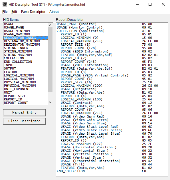
If you need to create your own HID report structure then you’ll probably need this tool. Just save your work often and keep backups!
Custom HID devices
A custom HID device doesn’t conform to any of the known standard HID device reports. It’s not a mouse and not a keyboard. It’s your own ‘thing’. You get to decide on the content of the data packets that you will exchange with the host. If your data conforms to a standard unit defined in the HID class such as voltage, mass, time and many others then you can have that. Or if it’s just plain bytes then you can have those too. Most importantly you do not have to create a USB device driver on the host but you will have to use low level host APIs to communicate with your device.
Let’s have a look at an example HID descriptor that I could use for a custom device that can send and receive reports to and from the host.
enum {
  IN_REPORT_SIZE = 12,   // 1 byte report id + 11-byte report
  OUT_REPORT_SIZE = 10,  // 1 byte report id + 9-byte report
};

const uint8_t reportDescriptor[32] = {
  0x05, 0x01,                    // USAGE_PAGE (Generic Desktop)
  0x09, 0x00,                    // USAGE (Undefined)
  0xa1, 0x01,                    // COLLECTION (Application)

  0x15, 0x00,                    //   LOGICAL_MINIMUM (0)
  0x26, 0xff, 0x00,              //   LOGICAL_MAXIMUM (255)

  // IN report

  0x85, 0x01,                    //   REPORT_ID (1)
  0x75, 0x08,                    //   REPORT_SIZE (8)
  0x95, IN_REPORT_SIZE-1,        //   REPORT_COUNT (this is the byte length)
  0x09, 0x00,                    //   USAGE (Undefined)
  0x81, 0x82,                    //   INPUT (Data,Var,Abs,Vol)

  // OUT report

  0x85, 0x02,                    //   REPORT_ID (2)
  0x75, 0x08,                    //   REPORT_SIZE (8)
  0x95, OUT_REPORT_SIZE-1,       //   REPORT_COUNT (this is the byte length)
  0x09, 0x00,                    //   USAGE (Undefined)
  0x91, 0x82,                    //   OUTPUT (Data,Var,Abs,Vol)

  0xc0                           // END_COLLECTION
};
The above example shows how I define the two reports. The LOGICAL_MINIMUM and LOGICAL_MAXIMUM declarations set up the host for receiving full range 8-bit bytes. I then go on to define the IN and OUT reports.
In USB terminology the direction of data transfer is always expressed relative to the host. Therefore IN reports come from the device to the host and OUT reports are sent out from the host to the device.
My first report definition, id #1 will be 12 bytes long. The first byte of the report buffer is always the report id (forgetting this is a common gotcha) and the remaining 11-bytes are whatever I want them to be.
The second report definition, id #2 is for data sent to the host. It’s defined in the same way and it’s a 10 byte report with 9 of those bytes available for user data.
HID reports are sent over interrupt endpoints and the maximum payload for an interrupt transfer is 64 bytes so if you have more to send then consider designing your protocol to break up your payload into 63 byte fragments and streaming them through the endpoint as a sequence of reports. If you have a lot more data to send, or you care about the bandwidth available to you, then perhaps your device is better suited to one of the other USB subprotocols because the full speed standard sets a limit of one 64-byte packet to be sent per millisecond.
USB devices on the F042
Now that we know a little bit about HID devices it’s time to look at what ST’s given us to work with on the F042 and there’s good and bad news here.
The USB peripheral supports version 1.1, which is full speed. The USB naming department totally failed and continue to fail to learn from the SCSI naming debacle and so we now have low, full, high and super speeds whatever the heck those subjective terms mean. As if today’s ‘super’ is going to be ‘super’ for evermore. Sigh.
The good news is that the USB peripheral on the F042 is little more than a PHY. Really, the highest level concept that it understands is that of the endpoint. All you really need to do is set up the device registers including those that define the endpoints and then I/O consists of reading from and writing to some dedicated FIFO registers. Interrupts are provided to let you know what’s going on that’s just about it. With no attempt to provide any higher level protocol support there are no constraints on the type of USB device that you could implement.
The not so good news is that ST’s ‘Cube’ library support is not particularly efficient. They’ve tried to be too generic as if they’re writing PC library code and the result is bloated compilation sizes and some truly horrendous ‘C’ macros that deserve an entry into the annual IOCC contest. For example, this innocent looking macro:
PCD_SET_EP_DBUF0_CNT(hpcd->Instance, ep->num, ep->is_in, len)expands through 7 steps of nesting to all of this:
{ \
    if((ep->is_in) == PCD_EP_DBUF_OUT)\
      /* OUT endpoint */ \
    {{\
    uint16_t *pdwReg = ((uint16_t *)(((((hpcd->Instance)))->BTABLE+(((ep->num)))*8+2)+  ((uint32_t)(((hpcd->Instance))) + 0x400))); \
    {\
    uint16_t wNBlocks;\
    if((((len))) > 62){{\
    (wNBlocks) = ((((len)))) >> 5;\
    if((((((len)))) & 0x1f) == 0)\
      (wNBlocks)--;\
    *pdwReg = (uint16_t)(((wNBlocks) << 10) | 0x8000);\
  };}\
    else {{\
    (wNBlocks) = ((((len)))) >> 1;\
    if((((((len)))) & 0x1) != 0)\
      (wNBlocks)++;\
    *pdwReg = (uint16_t)((wNBlocks) << 10);\
  };}\
  };\
  };} \
    else if((ep->is_in) == PCD_EP_DBUF_IN)\
      /* IN endpoint */ \
      *((uint16_t *)((((hpcd->Instance))->BTABLE+((ep->num))*8+2)+  ((uint32_t)((hpcd->Instance)) + 0x400))) = (uint32_t)(len);  \
  }
I abandoned the idea of using the Cube/HAL libraries except for reference and implemented a custom HID device using my stm32plus library and bare register access to the USB peripheral.
Testing USB devices
Testing a USB device is by no means straightforward. The protocol defines strict timing requirements for state changes and response times, some of which are sub-second. When I was developing the custom HID support for stm32plus debugging it was difficult. As soon as you pull DP high to signal device insertion then it will start raining requests from a very impatient host.
Breakpoints set during this device enumeration stage are typically one-shot. That is, you can hit the breakpoint you need when you need it but when you pause to look at the state in the debugger then the host will quickly get upset and fail enumeration so you have start all over again for further debugging.
What we need is a tool that can spy on the protocol and as luck would have it there is one and it’s free. Download and install a copy of Microsoft Message Analyzer.
Here’s a quick tutorial on how to setup and use the tool to debug a USB device.
Microsoft Message Analyzer
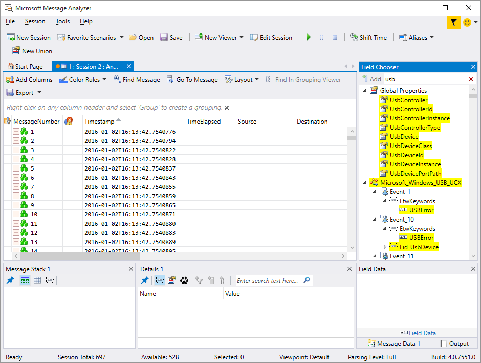
The first step is to run the tool and you’ll see the main screen looking like this.
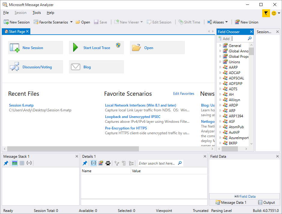
I’ve closed the View Filter tool window because I don’t need it and opened up the Field Chooser window (Tools -> Windows -> Field Chooser).
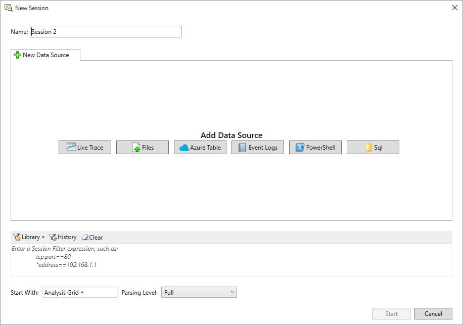
Click on the New Session button and you’ll get a dialog box.
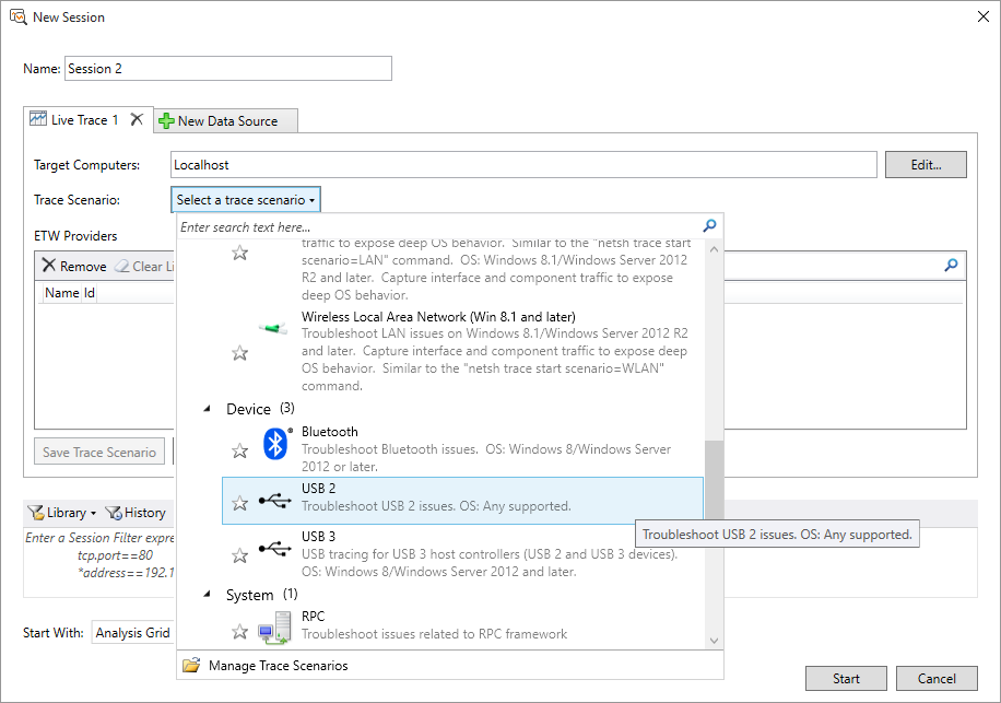
Click on the Live Trace button and then from the Trace Scenario drop-down box select USB 2 if you’ll be plugging into a USB 2 hub or USB 3 if you’re plugging into a USB 3 hub.
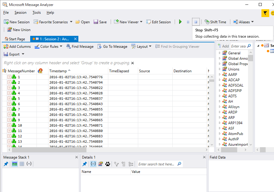
There’ll be a short pause while it fills in some provider information and then you can click Start to get started. The main window will quickly fill up with data. Locate the Stop icon in the toolbar and press it.
Now that data collection is stopped we will customise the view to contain only USB device information. Close the Session Explorer tool window and type ‘usb’ into the Field Chooser text box to filter the options like this:
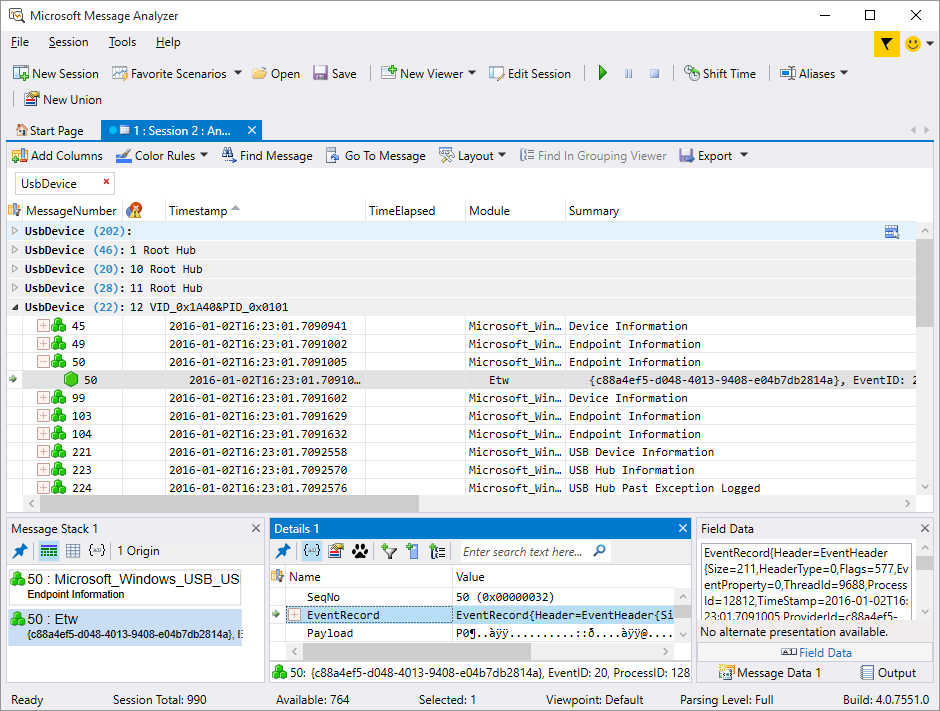
Double-click on all the fields that start with ‘UsbDevice’ so that they are added to the main window. The Source and Destination fields are of no use so right-click on those column headers and select Remove so that they disappear. Now find the UsbDevice column header, right click on it and select Group. This is the key step to understanding message flow as it will separate out devices by their PID/VID combination. The Field chooser can now be closed to maximise your screen area for actual data.
You are now ready to run some debugging sessions. Basically I run a debugging session like this:
- Start the Eclipse/OpenOCD debug session. During the flash programming stage the device will disconnect from the PC and I’ll get the ‘ding-dong’ sound from Windows as a confirmation.
- The program is automatically halted by the debugger after reset so now I click the start option (F5) in the analyser tool. Data is now being collected.
- I release my program in Eclipse and whatever I’m debugging will happen.
- When I’m happy that I’ve gone past the point where I’ve exchanged the data I want with the host then I go back to the tool and click stop (Shift-F5). I can now analyse the data I’ve collected.
With the tool paused you can analyse everything that happened during the session in minute detail, including the entire enumeration stage. And the great thing is that the display remembers the devices that you have expanded for viewing between sessions so you can just run it over and over again and only your device will be expanded for viewing in the window. Here’s a snapshot of my custom HID example starting up.
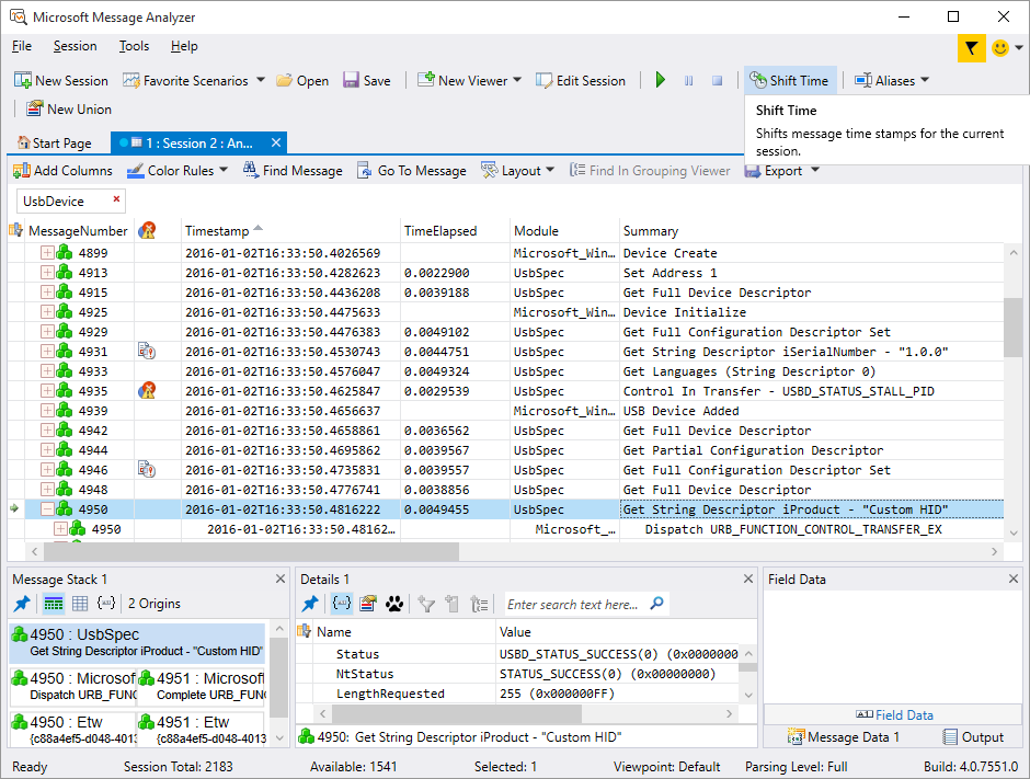
You can clearly see the sequence of descriptors being requested by the host and the responses from my device. When you’re debugging USB you will quickly become intimately familiar with those descriptors.
Finally let’s take a look beyond device enumeration and into device report data exchange with the host. My sample code wakes up every second and sends the string ‘Hello World’ to the host as report id #1. If you refer back to the custom HID report descriptor that I showed earlier you’ll recall that I defined report #1 (IN to the host) as having 12 bytes. That’s 1 byte for the mandatory report ID and the remaining 11 for the string ‘Hello World’. Here is that transfer in the analyser tool:
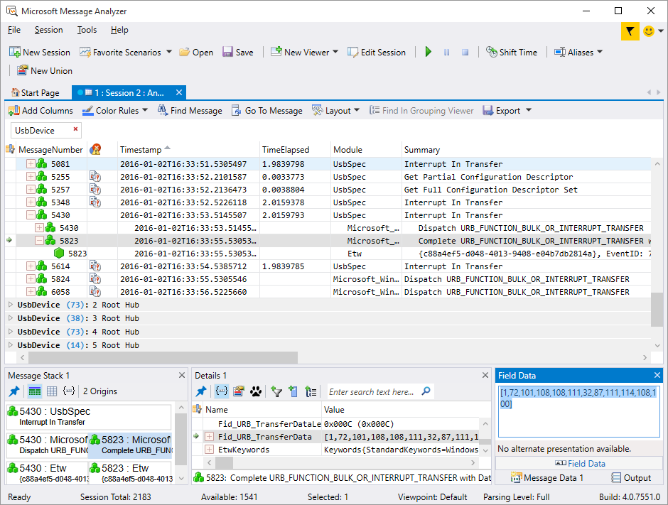
To see the data you drill down into the Interrupt In Transfer entry and find the Fid_URB_TransferData line. In the Field Data window you’ll see the actual bytes that the host received.
In summary, the free Microsoft Message Analyzer is a vital tool for USB debugging and I would not be without it for a second.
Using the stm32plus custom HID driver
After completing the USB driver code I merged it into the stm32plus C++ library so that you can produce your own custom HID implementation with little effort. A direct link to the device driver template is here.
I was pleased with the efficiency of the results. I managed to get a bare-bones program size of just 5808 bytes versus the same program taking 10796 bytes using ST’s Cube/HAL. Both were compiled with gcc using the -Os optimisation option.
The full stm32plus custom HID example can be found here. Let’s take a look at how it fits together.
Configuring your device
The main template, UsbCustomHid is parameterised with a type that contains some important constants that the template will refer to. Let’s see them:
struct MyHidConfiguration {

  enum {

    /*
     * USB Vendor and Product ID. Unfortunately commercial users will probably have to pay
     * the license fee to get an official VID and 64K PIDs with it. For testing and hacking
     * you can just do some research to find an unused VID and use it as you wish.
     */

    VID = 0xF055,
    PID = 0x7201,

    /*
     * IN and OUT are always with respect to the host. You as a device transmit on an IN
     * endpoint and receive on an OUT endpoint. Define how big your reports are here. 64-bytes
     * is the maximum allowed.
     *
     * Report id #1 is for reports TO the host (IN direction)
     * Report id #2 is for reports FROM the host (OUT direction)
     */

    IN_ENDPOINT_MAX_PACKET_SIZE = 12,   // 1 byte report id + 11-byte report
    OUT_ENDPOINT_MAX_PACKET_SIZE = 10,  // 1 byte report id + 9-byte report

    /*
     * The number of milliamps that our device will use. The maximum you can specify is 510.
     */

    MILLIAMPS = 100,

    /*
     * Additional configuration flags for the device. The available options that can be
     * or'd together are UsbConfigurationFlags::SELF_POWERED and
     * UsbConfigurationFlags::REMOTE_WAKEUP.
     */

    CONFIGURATION_FLAGS = 0,      // we want power from the bus

    /*
     * The language identifier for our strings
     */

    LANGUAGE_ID = 0x0809    // United Kingdom English.
  };

  /*
   * USB devices support a number of Unicode strings that are used to show information
   * about the device such as the manufacturer, product, serial number and some other
   * stuff that's not usually as visible to the user. You need to define all 5 of them
   * here with the correct byte length. Look ahead to where these are defined to see
   * what the byte lengths will be and then come back here and set them accordingly.
   */

  static const uint8_t ManufacturerString[32];
  static const uint8_t ProductString[22];
  static const uint8_t SerialString[12];
  static const uint8_t ConfigurationString[8];
  static const uint8_t InterfaceString[8];
};
The constants can be changed to suit your application, but remember the overall 64-byte report size limit. I won’t dwell on the politics of the VID/PID assignment policy here. If you want to know more then google will help you find the many articles already written on that subject. This hackaday article is a good place to start.
The official language identifers PDF can be found here. For example English (US) is 0x0409.
We can now declare a USB HID device class instance.
/*
 * Declare the USB custom HID object. This will initialise pins but won't
 * power up the device yet.
 */

UsbCustomHid<MyHidConfiguration> usb;
As the comment says, the constructor will attach PA11 and PA12 to the USB peripheral and do nothing else. Before we start the peripheral we need to subscribe to the events that will be raised during your device’s lifecycle.
Communication and status event handlers
stm32plus does all its callbacks using strongly typed event handlers implemented under the hood using Don Clugston’s famous fasted possible C++ delegates code. From the point of view of the user this gives an elegant, type-safe and scoped subscribe/unsubscribe programming model.
/*
 * Subscribe to all the events
 */

usb.UsbRxEventSender.insertSubscriber(UsbRxEventSourceSlot::bind(this,&UsbDeviceCustomHid::onReceive));
usb.UsbTxCompleteEventSender.insertSubscriber(UsbTxCompleteEventSourceSlot::bind(this,&UsbDeviceCustomHid::onTransmitComplete));
usb.UsbStatusEventSender.insertSubscriber(UsbStatusEventSourceSlot::bind(this,&UsbDeviceCustomHid::onStatusChange));
The UsbCustomHid class raises three event types that can be subscribed to. The TX and RX complete events are important so that you can schedule your communication with the host. When the host has sent you a report and it’s all been received then you’ll get the RX complete event.
When you send a report to the host it is done asynchronously with a non-blocking call and when that transmission completes then you’ll get a TX complete event.
The status event is used to notify you whenever there’s been a change to the status of the connection such as would happen during device insertion and removal. In particular, the move into and away from the CONFIGURED state is critical because you can only communicate with the host during the CONFIGURED state. At the very least, you will need to look for a change into and away from that state.
In the example code my implementation of the onReceive event handler looks like this.
/*
 * Data received from the host
 */

void onReceive(uint8_t endpointIndex,const uint16_t *data,uint16_t size) {

  // note that the report data is always prefixed with the report id, which is
  // 0x02 in the stm32plus custom HID implementation for reports OUT from the host

  if(endpointIndex==1 && size==10 && memcmp(data,"\x02stm32plus",size)==0)
    _receivedReportTime=MillisecondTimer::millis();
}
I check that the endpoint index is the one that I expect and that the report has the expected size and content. I then set a flag for the main loop to pick up on and flash a LED to let the user know the report was received.
The onReceive handler is called within an IRQ context so it’s important that you keep the CPU cycles to a minimum and be aware of the data sychronization issues with non-IRQ code that can occur.
To keep the performance at the highest level possible data reception is done with zero-copy semantics which means that the data pointer points directly into the USB peripheral FIFO. If you need to process the data beyond the scope of the event handler then it must be copied out of the address pointed to bydata.
In my example I don’t really need to know when data transmission is complete because I’m sending a report every 1000ms which is way more than the report transmission time. I implement a skeleton event handler anyway just so that you can see what it looks like:
/*
 * Finished sending data to the host
 */

void onTransmitComplete(uint8_t /* endpointIndex */,uint16_t /* size */) {
  // ACK received from the host
}
Again, this event handler is called within an IRQ context so you must be sure to do as little as possible before returning.
The implementation of the onStatusChange handler is more involved.
/*
 * Device status change event
 */

void onStatusChange(UsbStatusType newStatus) {

  switch(newStatus) {

    case UsbStatusType::STATE_CONFIGURED:
    _deviceConfigured=true;
    _lastTransmitTime=MillisecondTimer::millis()+5000;    // 5 second delay before starting to send
    break;

    case UsbStatusType::STATE_DEFAULT:
    case UsbStatusType::STATE_ADDRESSED:
    case UsbStatusType::STATE_SUSPENDED:
      _deviceConfigured=false;
      break;

    default:     // keep the compiler quiet
      break;
  }
}
This implementation looks for state changes in and out of CONFIGURED. Any other state means that the host is not ready to talk to us. As with the TX/RX event handlers this is called within the context of an IRQ so minimal work must be done here before returning.
With those three handlers implemented you are almost good to go with your USB device but last of all you need to implement the strings that identify your device.
USB strings
During the device enumeration phase you get the opportunity to supply some strings, in a language of your choice, that describe the facets of your device. My custom HID device driver requires that you supply manufacturer and product names, serial number and descriptions for your configuration and interface.
Here’s the strings I used in the example code.
/*
 * These are the USB device strings in the format required for a USB string descriptor.
 * To change these to suit your device you need only change the unicode string in the
 * last line of each definition to suit your device. Then count up the bytes required for
 * the complete descriptor and go back and insert that byte count in the array declaration
 * in the configuration class.
 */

const uint8_t UsbDeviceCustomHid::MyHidConfiguration::ManufacturerString[sizeof(UsbDeviceCustomHid::MyHidConfiguration::ManufacturerString)]={
  sizeof(UsbDeviceCustomHid::MyHidConfiguration::ManufacturerString),
  USB_DESC_TYPE_STRING,
  'A',0,'n',0,'d',0,'y',0,'\'',0,'s',0,' ',0,'W',0,'o',0,'r',0,'k',0,'s',0,'h',0,'o',0,'p',0
};

const uint8_t UsbDeviceCustomHid::MyHidConfiguration::ProductString[sizeof(UsbDeviceCustomHid::MyHidConfiguration::ProductString)]={
  sizeof(UsbDeviceCustomHid::MyHidConfiguration::ProductString),
  USB_DESC_TYPE_STRING,
  'C',0,'u',0,'s',0,'t',0,'o',0,'m',0,' ',0,'H',0,'I',0,'D',0
};

const uint8_t UsbDeviceCustomHid::MyHidConfiguration::SerialString[sizeof(UsbDeviceCustomHid::MyHidConfiguration::SerialString)]={
  sizeof(UsbDeviceCustomHid::MyHidConfiguration::SerialString),
  USB_DESC_TYPE_STRING,
  '1',0,'.',0,'0',0,'.',0,'0',0
};

const uint8_t UsbDeviceCustomHid::MyHidConfiguration::ConfigurationString[sizeof(UsbDeviceCustomHid::MyHidConfiguration::ConfigurationString)]={
  sizeof(UsbDeviceCustomHid::MyHidConfiguration::ConfigurationString),
  USB_DESC_TYPE_STRING,
  'c',0,'f',0,'g',0
};

const uint8_t UsbDeviceCustomHid::MyHidConfiguration::InterfaceString[sizeof(UsbDeviceCustomHid::MyHidConfiguration::InterfaceString)]={
  sizeof(UsbDeviceCustomHid::MyHidConfiguration::InterfaceString),
  USB_DESC_TYPE_STRING,
  'i',0,'t',0,'f',0
};
USB strings are made up of 16-bit Unicode characters without ‘C’-style null terminators. Handily for English-speaking westeners the lower Unicode code points map directly to the printable ASCII range so all we need to do is expand those characters to 16-bits to have a valid Unicode code point. The sample strings serve as a base for you to copy-paste into your own code.
The manufacturer, product name and serial number should be obvious. Don’t expect these to be displayed by the Windows Device Manager though because it will use the generic USB Input Device name supplied by Microsoft’s universal HID driver.
The configuration and interface strings are less obvious and you can learn more about what they are by clicking on the links. The stm32plus driver provides one configuration and one interface. I’ve never seen Windows display these strings anywhere in the user interface.
Starting the device
OK so you’ve done all the prep work and you’re ready to tell the host that you exist. To do that you just need to call the start() method.
/*
 * Start the peripheral. This will pull up the DP line which is the trigger for the host
 * to start enumeration of this device
 */

usb.start();
This will enable the pull-up resistor on the D+ line that prompts the host to begin the enumeration process and enable your device. You will get control back immediately. Everything else from here is interrupt driven.
There’s an equivalent stop() that can be used to do a software disconnect of the device and this can be useful in testing to ensure that you handle the case where a user uses the safely remove hardware system tray option to disconnect your device without cutting the power.
Sending reports to the host
The method on the UsbCustomHid class that sends a report to the host is sendReport(), an example of which is shown here.
usb.sendReport("\x01Hello World",12);Note how the data being sent is prefixed with the single byte report identifier. Very important. Don't forget this. If your report is smaller than the 64-byte maximum packet size for an interrupt transfer, and I recommend that they are, then your report will be copied into the USB peripheral's internal memory before this method returns so you don't have to keep the data in scope.
The peripheral will begin the process of sending the report data to the host and you will be notified when it's complete via the TX complete event handler. You cannot send another report until the previous report has been sent and you cannot exceed the maximum bandwidth for interrupt transfers of 64-bytes per millisecond.
Custom HID interaction with the PC
A custom HID is, well, custom. The host has no idea how to process the data that's being exchanged so you need to write application code on the PC to communicate with your device. Thankfully you don't need to write a device driver so there are no installation steps that require admin rights on the user's PC. If you're producing a device for the corporate environment then this is one major headache avoided.
Interacting with a USB device on the PC is a little bit tricky if you've never had cause to work directly with hardware devices before. The good news is that once you've located your device you can interact with it through the usual CreateFile, ReadFile and WriteFile Win32 APIs and by extension that means you can also get at the device using C#. In these examples I'll be using C++ so that we can see all the detail.
Find your device name
USB devices on the PC have special filenames that encode, amongst other things, the VID and PID codes. In my example code I am using VID 0xF055 and PID 0x7201. My device name will look like this:
\\?\hid#vid_f055&pid_7201#7&23588de&0&0000#{4d1e55b2-f16f-11cf-88cb-001111000030}Ugly huh? These special filenames are not meant to be seen by humans although you can piece together the filename from the strings visible in the device manager entry for your USB device. The correct way to get this name is to enumerate all the attached devices and query for the filename when you find your device.
Here's a copy-and-pastable C++ class to do just that. It has dependencies on the venerable MFC CString class as well as the <stdint> header. Both of these dependencies are easily replaceable if you so wish.
class UsbEnumerate {

public:
  CString _path;

public:
  UsbEnumerate(uint16_t vid,uint16_t pid);

  const CString& getPath() const;
};


/*
 * Get the path to the device or empty string if not found
 */

inline const CString& UsbEnumerate::getPath() const {
  return _path;
}


/*
 * Search for the device and set the path
 */

inline UsbEnumerate::UsbEnumerate(uint16_t vid,uint16_t pid) {

  HDEVINFO                         hDevInfo;
  SP_DEVICE_INTERFACE_DATA         DevIntfData;
  PSP_DEVICE_INTERFACE_DETAIL_DATA DevIntfDetailData;
  SP_DEVINFO_DATA                  DevData;
  DWORD dwSize,dwMemberIdx;
  TCHAR devid[100];
  GUID InterfaceClassGuid = GUID_DEVINTERFACE_HID;

  wsprintf(devid,_T("vid_%04hx&pid_%04hx"),vid,pid);

  // We will try to get device information set for all USB devices that have a
  // device interface and are currently present on the system (plugged in).

  hDevInfo=SetupDiGetClassDevs(&InterfaceClassGuid,NULL,0,DIGCF_DEVICEINTERFACE|DIGCF_PRESENT);

  if(hDevInfo!=INVALID_HANDLE_VALUE) {

    // Prepare to enumerate all device interfaces for the device information
    // set that we retrieved with SetupDiGetClassDevs(..)
    DevIntfData.cbSize=sizeof(SP_DEVICE_INTERFACE_DATA);
    dwMemberIdx=0;

    // Next, we will keep calling this SetupDiEnumDeviceInterfaces(..) until this
    // function causes GetLastError() to return  ERROR_NO_MORE_ITEMS. With each
    // call the dwMemberIdx value needs to be incremented to retrieve the next
    // device interface information.

    SetupDiEnumDeviceInterfaces(hDevInfo,NULL,&InterfaceClassGuid,dwMemberIdx,&DevIntfData);

    while(GetLastError()!=ERROR_NO_MORE_ITEMS) {

      // As a last step we will need to get some more details for each
      // of device interface information we are able to retrieve. This
      // device interface detail gives us the information we need to identify
      // the device (VID/PID), and decide if it's useful to us. It will also
      // provide a DEVINFO_DATA structure which we can use to know the serial
      // port name for a virtual com port.

      DevData.cbSize=sizeof(DevData);

      // Get the required buffer size. Call SetupDiGetDeviceInterfaceDetail with
      // a NULL DevIntfDetailData pointer, a DevIntfDetailDataSize
      // of zero, and a valid RequiredSize variable. In response to such a call,
      // this function returns the required buffer size at dwSize.

      SetupDiGetDeviceInterfaceDetail(hDevInfo,&DevIntfData,NULL,0,&dwSize,NULL);

      // Allocate memory for the DeviceInterfaceDetail struct

      DevIntfDetailData=(PSP_DEVICE_INTERFACE_DETAIL_DATA)HeapAlloc(GetProcessHeap(),HEAP_ZERO_MEMORY,dwSize);
      DevIntfDetailData->cbSize=sizeof(SP_DEVICE_INTERFACE_DETAIL_DATA);

      if(SetupDiGetDeviceInterfaceDetail(hDevInfo,&DevIntfData,DevIntfDetailData,dwSize,&dwSize,&DevData)) {
        // Finally we can start checking if we've found a useable device,
        // by inspecting the DevIntfDetailData->DevicePath variable.
        // The DevicePath looks something like this:
        //
        // \\?\usb#vid_04d8&pid_0033#5&19f2438f&0&2#{a5dcbf10-6530-11d2-901f-00c04fb951ed}
        //
        // As you can see it contains the VID/PID for the device, so we can check
        // for the right VID/PID with string handling routines.

        if(_tcsstr((TCHAR*)DevIntfDetailData->DevicePath,devid)!=NULL) {

          _path=DevIntfDetailData->DevicePath;
          HeapFree(GetProcessHeap(),0,DevIntfDetailData);
          break;
        }
      }

      HeapFree(GetProcessHeap(),0,DevIntfDetailData);

      // Continue looping
      SetupDiEnumDeviceInterfaces(hDevInfo,NULL,&InterfaceClassGuid,++dwMemberIdx,&DevIntfData);
    }

    SetupDiDestroyDeviceInfoList(hDevInfo);
  }
}
Make sure you add the following lines to your stdafx.h file so that you get the HID GUID declaration and the linker pulls in the .lib file for the setup API functions.
#include <initguid.h>
#include <hidclass.h>

#pragma comment(lib,"setupapi")
Here's an example of how to use the UsbEnumerate class.
UsbEnumerate usb(0xF055,0x7201);
HANDLE deviceHandle;

if(usb.getPath().IsEmpty())
  MessageBox(_T("Cannot find USB device. Please ensure that it's switched on and connected to the PC"));
else {

  // open the device

  if((deviceHandle=CreateFile(
                      usb.getPath(),
                      GENERIC_READ | GENERIC_WRITE,
                      FILE_SHARE_READ | FILE_SHARE_WRITE,
                      NULL,
                      OPEN_EXISTING,
                      FILE_FLAG_OVERLAPPED,
                      NULL))==INVALID_HANDLE_VALUE) {
    MessageBox(_T("The USB device has been located but we failed to open it for reading"));
  }
}
Now that you've got a handle to the device you can start reading and writing data. I use overlapped asynchronous IO to talk to the device so that the application can do other things while waiting for IO to complete.
Writing reports to the device
Writing a report to the device is as simple as using the WriteFile Win32 API call to send the data. Here's an example where I use the overlapped IO functionality to asynchronously write a 10 byte report to the device. The report data consists of the mandatory report ID number, which as you'll remember from the previous paragraphs is #2 for OUT reports in my report descriptor.
// NB: _dataOutEvent and _exitEvent are manual reset CEvent classes.

DWORD dwWritten,retval;
OVERLAPPED overlapped;
HANDLE h[2];

ZeroMemory(&overlapped,sizeof(overlapped));
overlapped.hEvent=_dataOutEvent;

h[0]=_dataOutEvent;
h[1]=_exitEvent;

static const char *report="\x02stm32plus";

if(!WriteFile(_deviceHandle,report,10,&dwWritten,&overlapped)) {

  if(GetLastError()==ERROR_IO_PENDING) {
    if((retval=WaitForMultipleObjects(sizeof(h)/sizeof(h[0]),h,FALSE,INFINITE))==WAIT_OBJECT_0) {
      // IO has completed asynchronously (but we blocked waiting for it)
    }
    else if(retval==WAIT_OBJECT_0+1) {
      // exit event has been signalled elsewhere in program - we should quit
    }
  }
  else {
    // real error - handle it
  }
}
else {
  // IO has completed synchronously
}
Reading from the device is just the same workflow using an OVERLAPPED structure to indicate an event that should be signalled when the operation is complete.
Clocking a USB peripheral
The 12Mb/s USB data signalling rate is required by the standard to have an accuracy of +/- 0.25%. This is easily achievable with an external crystal but not so with the on-chip 8MHz oscillator used for many STM32 F0 applications as this has an accuracy of +/- 1%.
In my own measurements using an F051 device I found the internal 8MHz HSI clock to be ticking at 8.038MHz (about 0.5% off nominal) and to exhibit poor stability. In laymans terms that means the frequency was all over the place. The internal clock can be trimmed in 40kHz intervals and that may be one solution but a better one is to use the dedicated internal HSI48 clock and enable the clock recovery system (CRS) to have it automatically trimmed from the Start of Frame (SOF) packets sent to the device by the host every millisecond. On it's own the HSI48 clock is trimmed by ST at the factory to about 3% accuracy at 25°C so using it without CRS is not an option. Another neat feature is that you can output the trimmed clock on the MCO pin which is available on the larger pin packages to clock other peripherals within your design.
I explain how to set up the HSI48 with the CRS in my previous article, A development board for the STM32F042 TSSOP package. Search down for the Testing USB heading to see the code and explanation.
That's all
I hope you enjoyed this little walkthrough of one of the more difficult peripherals to program on the STM32. If you've any comments or short questions then please use the comments section below. For more involved questions then please use the forum.