Nokia N82 2.4 inch QVGA TFT on the Arduino

It’s been a few months now since I released the original two articles that detailed the design, build and optimised software library for the 2.0″ Nokia 6300 QVGA TFT connected to the Arduino Mega XMEM interface. Judging by the responses I’ve had, there’s a lot of you out there that are interested in connecting these mobile phone TFTs to your Arduinos.

Today we move on to reverse-engineer another Nokia QVGA TFT. This time we’re going to tackle the Nokia N82. Read on to find out how I got on.

The N82 TFT

The N82 TFT is a 2.4″ panel that’s also found in the N77, N78, N79, E66, E52, E75 and 6210S. It’s certainly clear that back in the not-so-distant past when Nokia was the clear market leader in mobile phones they certainly knew how, as a company, to take a successful design and keep re-releasing it over and over again with small tweaks to keep the income rolling in. Replacement N82 panels are available at the time of writing for as low as £3 on ebay.


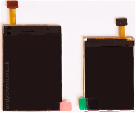
Two TFTs. The N82 next to the 6300.

You can get an idea of the physical size difference between the 2.4″ and 2.0″ panels from the above photograph. The resolution is identical, the pixels are simply larger on the N82 panel. Pixel densities are around 200ppi for the 6300 and 167ppi for the N82. Having a higher pixel density means that your graphics appear smoother. Having a lower pixel density makes your text larger, and perhaps more readable.

The schematic and the connector

It must be our lucky day because the pinout to the N82 is identical to the 6300 and it uses the same 24-pin board-to-board connector too! The 0.4mm pitch connector is made by JST and the part number is 24R-JANK-GSAN-TF. Here’s the datasheet.

It is easy to obtain them either direct from JST’s online shop or in small quantities from online sources. Here are some direct links to the ones that I know of:

gsmserver.com
cellnetos.com
stellatech.com

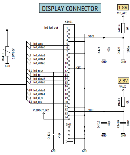
The pinout for the connector is shown here:

Here’s a photograph of the connector plug. If you look closely you can see where the ground pins connect directly into the ‘ground pour’ inside the ribbon cable. This helps to identify where pin 1 is located when doing the reverse engineering.


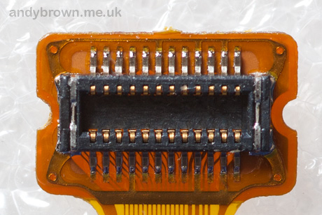
The connector on the LCD FPC cable

The backlight

The backlight shares the same design as the 6300 in that it consists of four white LEDs in series. Therefore we will use the same NCP5007 constant current LED driver from OnSemi that we’ve been using in all our Nokia TFT designs so far.


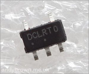
The NCP5007 in SOT23-5 package

The NCP5007 will be configured to supply a constant 20mA through the backlight circuit and we will use a PWM signal on the ENABLE pin to vary the brightness. The NCP5007 really is a wonderful little device – truly one of those things that ‘just works’ and I’ll use it wherever I need to drive up to 5 LEDs.

The development board schematic

We’ll gloss over the explanation of how we drive the TFT controller using the Arduino Mega XMEM interface because that’s all been explained in this article and there are no changes to the interface in this design.


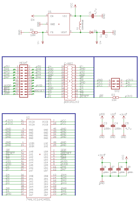
The Eagle schematic, click to download a PDF.

Just as before, we choose to use the 74ALVC164245 16-channel level converter from NXP to handle the conversion of the 5V signals from the Arduino down to a safe level of 3.3V where they won’t damage the panel.


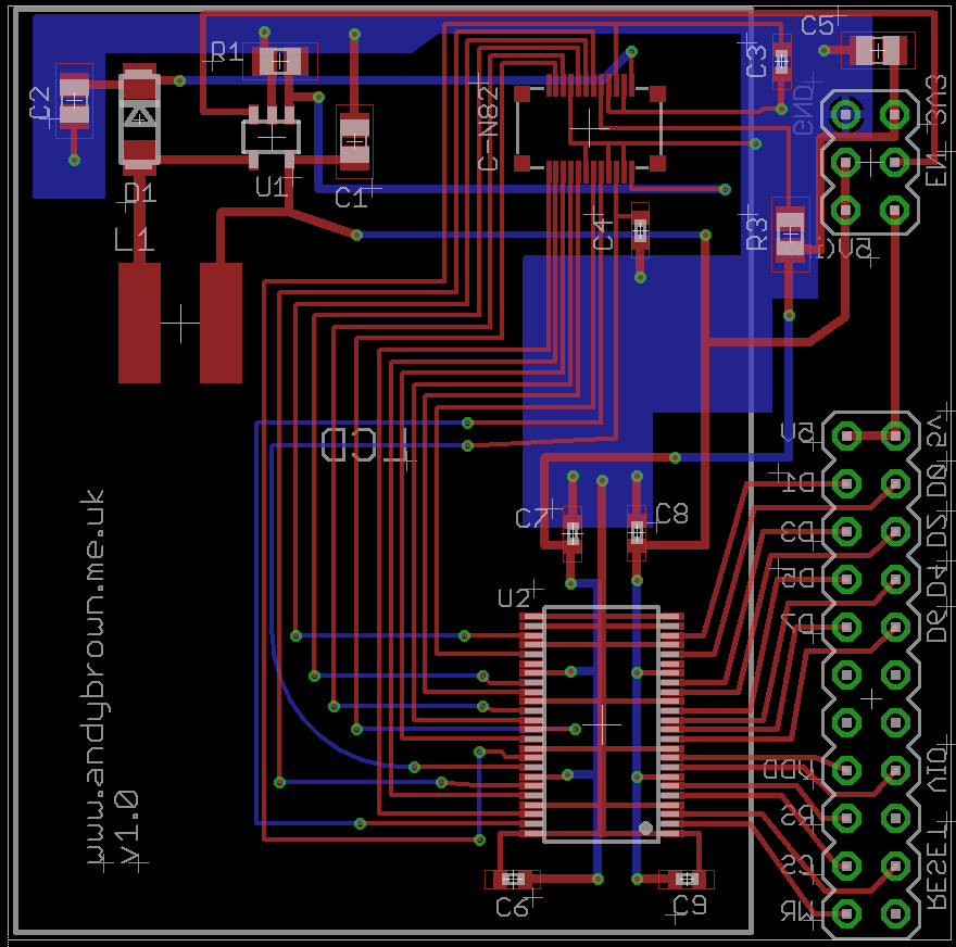
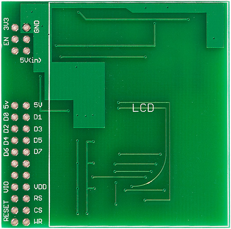
The Eagle PCB design, click for larger.

In this design I’m using the TSOP-48 (0.5mm) pitch version of the level converter rather than the SSOP-48 (0.635mm) pitch that I used in the 6300 design. The reason for the change is that the TSOP-48 package is more readily available from the suppliers that I use.

Another slight change, again due to parts availability, is the inductor. I’ve switched to a slightly different model that has a larger footprint but is otherwise functionally identical to the one I was using before.

Bill of Materials

Here’s a full list of parts used in this development board.

Part Value Device Package
C-N82 NOKIA12X2 24R-JANK-GSAN-TF 12X2
C1,C5 4.7µF ceramic 0805
C2 1µF ceramic 50V 0805
C3,C4,C6,C7,C8,C9 100nF ceramic 0603
D1 Diodes Inc. BO530W-7 schottky SOD-123
L1 Sumida 22µH CDRH5D28NP-220NC 6x6mm
MEGA pin header MA12-2 MA12-2
R1 10Ω 1% resistor 0805
R3 33KΩ resistor 0805
SV2 pin header MA03-2 MA03-2
U1 NCP5007 NCP5007 SOT23-5
U2 74ALVC164245DGG level converter TSOP48

The development board

I generated the Gerber’s from Eagle and sent them off to ITead Studio to be printed using their very good value prototype PCB service. A few weeks later they arrived and all were perfect, just as I’ve come to expect.


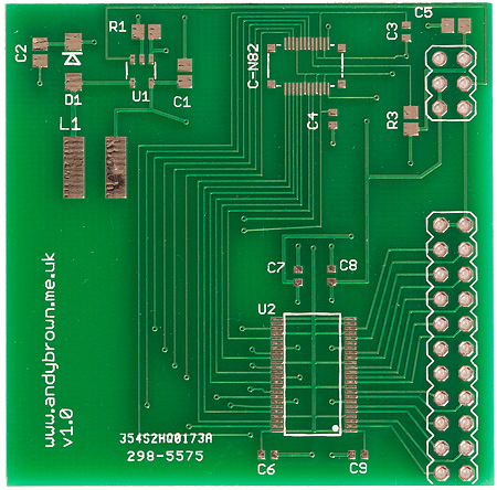
The front of the PCB. The pads are not gold, the tungsten lighting used in the photograph just makes them look like they are.


The back of the PCB

Building the board is a familiar process for me by now. In case you’re interested, this is the procedure that I follow.

  1. Flux the pads then tin them with an iron so they all have little solder bumps on them. For the level converter and the connector this means loading up the tip of the iron with solder and lightly dragging it over the pads.
  2. Use a very small amount of paste flux as a glue to hold down the level converter, connector and inductor in place on the board. Overdoing the flux can cause bubbling during the reflow which will cause the component to move out of position (very bad).
  3. Heat the board with the three parts on a hot-plate until the solder reflows and the parts sit down into position.
  4. Inspect the joints under a microscope and use a fine-tip iron to touch each one that shows any movement when prodded with a pin. There will be at least one…
  5. Use tweezers and a hot-air gun to reflow the other components into place.
  6. Clean the board with soapy water and a toothbrush then leave for at least 24 hours in the airing cupboard to dry out.
  7. Solder the 2.54mm headers and test.

So it’s not a short process but the rewards are worth the effort. Here’s the fully built development board.


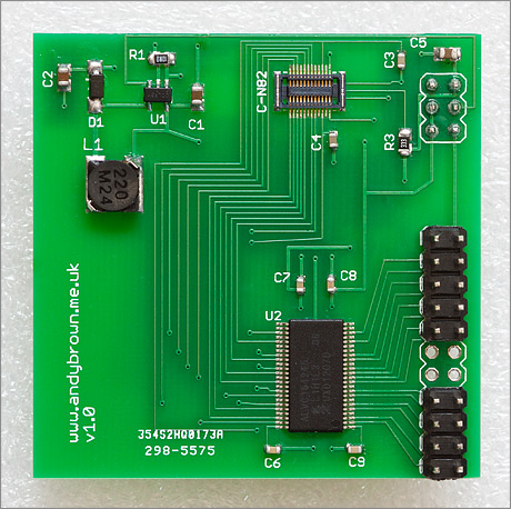
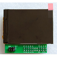
The board, fully built and awaiting the LCD

And here’s a shot with the LCD fitted. The 2.4″ display is a little oversized for the PCB but fits firmly and saves the additional cost of the larger PCB just to mount the screen.


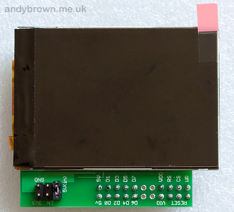
The board with the LCD attached.

Driver source code

My XMEM driver code has been updated to include support for the N82. You will need to download at least version 2.1.0 of the driver to get that support.

Because the panel is driven identically to the Nokia 6300, all the examples will work as-is with no changes. However, for completeness I have included “N82” driver names just in case I need to create specific customisations for this panel in the future.


#include "NokiaN82.h"

using namespace lcd;

typedef NokiaN82_Portrait_262K TftPanel;

The example snippet shows the driver name (NokiaN82_Portrait_262K ) and the header file (NokiaN82.h). Similar driver names for the Landscape orientation and 16M and 64K display modes (if supported by the panel) are included.

Another example

I created a full example that exercises the compressed graphics capability of the driver in a simulation of the output from a weather station on the Arduino. The source code is included in version 2.1.0 and above of the software driver.

This demo packs in 100Kb of compressed graphics in to the Atmega1280 and the controller code takes up a further 10Kb or so. The graphics are decompressed on-the-fly from flash by my LZG decoder routine included with the driver.

Here’s a video of the demo in action. Watch it here or click to watch in HD at YouTube.


Copyright Notices

The graphical weather images were downloaded from the Wikimedia Commons library. Please respect the rights of the original authors:

Snow image
Partly cloudy image
Rain image
Sun image

The numeric ‘temperature readout’ was created by typing the numbers 0..9 and the point and degree symbols into Wordpad in a nice font at 48 point size. Then I took a screenshot and used a paint program to crop out each character into its own bitmap and saved each one as a separate PNG.

I then ran the bm2rgbi utility included with the graphics library to convert the PNGs to LZG format and imported those binaries directly into the compiled flash image. You can see how that’s done by reading the example source code.

JPEG support now available

I’m pleased to announce driver support for displaying JPEG images. JPEG images may be compiled into flash and displayed from there or they may be streamed over an Arduino serial connection.

The driver documentation has been updated to include sample code and a demo video that shows you how to do it.

Here’s a link to the video that shows the JPEG decoder operating on images stored in flash. If you’d like to see it operating on JPEG images received over the serial link then please refer to the main driver documentation. The JPEG decoder is completely compatible with the Nokia 6300 as well as the N82.


Can I use it with the standard Arduino?

Yes you can, see this article for a write-up, including performance analysis and optimisations. The article is focused on the 6300 but the N82 works in exactly the same way.

Update: 23 September 2012

Another controller variant has turned up and we’re going to call this one ‘Type C’. It’s showing up in both 6300 and N82 screens. It behaves the same as Type A screens except for the following differences:

  • It won’t go into BGR colour transfer mode, only RGB is supported. Since RGB is supported by all variants I’ve seen RGB will become the default mode in my driver code from 2.2.0 onwards.
  • Page and column addresses are not reversed in landscape mode.

Type C panels are supported from version 2.2.0 of my driver code using a _TypeC suffix to the driver name. e.g. Nokia6300_Landscape_262K_TypeC.

Some boards for sale

I’ve constructed the remaining PCBs that I have and am selling them on a first come first served basis. The price including delivery is £16.90 for UK and £18.49 for anywhere else in the world. They come with the LCD fitted and are ready to plug in and play.

Temporarily out of stock! I’m building a new batch and expect to be completed on December 15th, 2012. Please check back here later.


Location


Print your own PCBs

Want to try assembling a board yourself but don’t have a home-etching kit? No problem, just download the Gerber files from my downloads page and use an online prototyping service such as that offered by Seeed Studio, ITead Studio or Elecrow.

  • atomsoft

    Beautiful work! Keep it up!

  • Jan

    Excellent job.
    Can you please let us know more how you found out all those details?
    e.g. how you found out the manufacturer of the connector, pinout connector and other details so that you were able to write a driver for that LCD?
    Congratulation!!

    Just a note: We are a wholesaler selling mobile phone spare parts and also various LCDs. You say N82 can be found in N77, N78, N79, E66, E52, E75 and 6210S. But from our experience there are also copies of LCDs and it need not be true that all those LCDs, if they work in one model, must also work in ALL others. I think there are different controllers and they can be different.

    • Thanks for the kind comments!

      Finding the manufacturer of the connector was luck. I bought a handful from Cellnetos and searched every datasheet from every manufacturer I could find but could not find one where the connector photos matched (there are several distinguishing features). Then someone who read my blog pointed me to the JST website and it really looked like a perfect match. He bought some and confirmed they matched so I went ahead and bought 100 from their online shop. Shipping is high but over 100 connectors it averages down well.

      How I found the pinout and the driver reverse engineering details are mostly detailed on my previous article about reverse engineering the Nokia 6300.

      I get these screens on ebay and for a seller to be sure that the LCD works in all the listed phones the pinout must be electrically the same but yes, it is possible that the controller could be different and the phone could issue a register-read to determine the controller and behave according to the results. So far the only difference I've seen between batches of screens is with the Nokia 6300 (it's detailed in my article and the difference was very minor).

      Hope this helps!

      • Jan

        Andy, thanks for the reply. But there are more different models of LCDs and 6300 is not the only difference; for example E65 should work with Nokia 6303. But not every LCD works on both. This month we received a batch of those LCDs and our customer tested them in 6303 mobile and they did not work. So I would guess there is a different controller. And we found ( during few years we sell LCD for mobiles) more differences. So it is not easy to write a driver for mobile LCDs and driver updating is never ending job 🙁

        Andy, in one of previvous articles http://andybrown.me.uk/2012/03/06/reverse-engi
        in
        Interrogating the controller paragraph
        you write you read registers of the controller. How did you know the controller’s registers address?
        Thanks for the reply.

        P.S. Just of of curiosity, how much time did you have to spend on these reverse engineering tasks to achieve the success?

        • I'm sure there are different controllers, I'm only interested in the ones that are advertised as compatible with the exact phones I'm targetting (2730, 6300, N82). Your retailers and their compatibility tests help me there by doing the testing 🙂

          I select the phone of interest by checking out ebay for a ready supply of cheap compatible panels and then googling for the official schematic. Given the schematic I can quite quickly locate the LCD interface because I know what the 8080 bus signals look like. Then I'll find the backlight driver on the schematic and use the component values to calculate the number of LEDs in it and from that I can choose a compatible constant-current device for my development board.

          The register indexes for an 8-bit controller are 0..255. To start reverse engineering you do the 8080 read protocol against every possible register address with a hard reset between each one in case you accidentally issue a command that puts it to sleep or something like that. As I noted in the writeup, read operations that did not yield a response were discarded.

          It probably took a day in all from seeing the read output to drawing on the display. It took much longer to do the Eagle design work and get the board made and the components selected and ordered; whole weeks went by there. The driver started off life as a port of the graphics library in my stm32plus package and quickly exceeded the initial capabilities. So much so that I'll be back-porting it back into stm32plus soon.

  • David

    Hi, nice job !
    I also reverse engineered the N81 about 6 months ago.
    In 2011 I was searching for some LCD for making some nice projects at home (It's just a hobbie). Then I found this: http://www.mikrocontroller.net/topic/62796 (In german)

    There I discovered the LCD controller MC2PA8201. Datasheet here: http://hw.cz/files/redaktor130/MC2PA8201pdf.pdf

    Based in the information of the N73 schematic and comparing it with other nokia phones, I saw that most of the phone shared the same parallel interface, so I gave a try and searched the biggest nokia screen I could found.
    The nokia N95 had and strange connector and the LCD for N95 8GB / N96 was too expensive, so I tried the N82.

    But suddenly the screen broke down by half ( Damn!!) so I bought another on ebay. But this time I bought a N82 display by mistake.
    But I remade the connections and it also worked!

    I bought the connector on ebay ($10/10 connectors). Search for "nokia lcd connector -flex".
    the "-flex" is for excluding the items with the word "flex" on its titles.
    I've searched it just now, and actually there's only one listing for the connector: http://www.ebay.com/itm/10-X-NEW-LCD-Connector-2x

    After displaying some images and text I no longer continued with it, since I was out of ideas or they were too complex 🙂

    Regards!

    • Just as an FYI: I don't think those connectors that you linked to on ebay are correct. Although it's hard to tell from the blurred photograph they are definitely missing some of the key features of the official JST connector – the main one being that the JST connectors have cutouts at the bottom and four "wing" grooves at each top corner. Cellnetos have a clear photograph of what the JST connector looks like:
      http://www.cellnetos.com/webshaper/pcm/pictures/s

  • Andrew

    I'd love to see someone try to hook this up to the Raspberry Pi! Add in a small keyboard and touchscreen overlay, and the raspi could be the single cheapest computer ever!

  • Guy Verachtert

    Hi Andy,
    This looks very interesting ! Will you ever consider building them again ?
    I've just seen there no longer in stock, and these are reel fun things for prototyping. 🙂

  • Please make more of these 🙂

    • I will do … ETA 2 weeks for the next batch

  • Steve

    Hi Andy Brown,
    Its a good job. I would like to give a view on the board. The board is a little bit oversize. I think you should consider trimming it in your next design. Also consider adding an ATMEGA on the board and a USBASP port thereby killing two birds with one stone. I don't know how to compile using the Arduino language. Can you offer this code in plain C language?

  • This is amazing, very inspiring, I've been spotting places I wanna put N82 LCD displays all week!

    Any chance of getting the PCB layout files? Since you don't have any boards left I'd love to get a couple from a PCB house and make some of these myself.

    Did you think about putting an atmega on-board? I think I'd like to do that and send it what to display via uart or spi – Though If I'm going to do that perhaps a 32bit mcu would be better… So many choices!

    The smallest I've hand soldered is an atmega128 with a 0.3mm leg and 0.8mm spacing – How does doing this compare? I'd rather not reflow but the LCD connector looks impossible to hand solder at 0.2mm with 0.4mm spacing!

    • Hi, thank you for your comments. I do have some more boards on the way and will build them to satisfy those that have been asking.

      I have considered a graphics co-processor, it would probably be an STM32F4 if I did do it, but I don't have any immediate plans that way.

      I have not tried to hand solder the 0.4mm pitch connector. I would imagine that you could do it with about 10x hands-free magnification, strong lighting and a sub-1mm iron tip. The legs are relatively long which helps because the plastic will melt if you hit it with the iron and it will not withstand the heat of a hot-air gun.

      From time to time I do release complete project files and Gerbers and in due course I will do so for these boards as well. It's a really simple circuit though and I do like to encourage innovation rather than cloning – it really amazes me what people such as yourself come up with when given the inspiration. But the CAD files will be released soon nevertheless.

  • jmv

    hello andy. very good this! but is compatible with n73 display? thank you

    • Hi, it is not compatible "out of the box" due to the different pinout on the N71/N73/N93. Keep checking back or subscribe to my youtube channel though because a writeup on the N93 is in the pipeline and that one is compatible with the N73.

  • jmv

    ok andy, thanks!

  • I'm sure there are different controllers, I'm only interested in the ones that are advertised as compatible with the exact phones

  • Mocio

    Great job man……!!!!! Is it possible to buy only the shield without the lcd??? I've already one! Please let me know! thanks!

    • Hi, thank you for your comment. At the moment all my cards have LCDs attached.

  • mamoonrizwan

    hello andy
    the NCP5007 Constant current source is not available in my area
    cani supply the LCD backlight with LM317 constant current source . if yes whats the voltage to be for LM317

    • Hi,

      The LM317 is a voltage regulator, not a constant current LED driver. If you can't source a constant current LED driver then you need to find another way to drive the 4 white LEDs in series. This will need a forward voltage of approx (3.2v x 4) to light up and then you need to control the current somehow, e.g. a series resistor.

      Another option would be to use the N95 8Gb display (see my write up) because that display has the backlight driver built-in.

  • mamoon

    i have desgined a LM317 tuned at 15 V output . is that ok for backlight supply???

    • Yes it is, the backlight will need at least 3.2 x 4 = 12.8V so you could try a series resistor of about (15 – 12.8) / 0.02 = 110 Ohms to get a current of 20mA through the backlight. The assumption here is that the forward voltage of the white LEDs is 3.2V and that's usually the case give or take a little.

  • Hi, Andy!

    Signals "VDD" and "VIO" along with other signals have an amplitude of 3.3V. ie VDD is not equal to 2.8, and VIO is not equal to 1.8.

    I want to connect to the STM32 to display (GPIO 3.3V). It turns 74ALVC164245 not needed?

    • Hi Kirill,

      Yes you're correct the 3.3V STM32 does not require the 74ALVC164245.

      • Kirill

        In this case, VDD should be connected to a separate voltage source 2.8V and VIO to 1.8V voltage source? That is, additionally put on board two DC/DC converter.

        After all, in your case, this current limiting circuits 74ALVC164245 .. If VDD and VIO connect to voltage 3.3V directly, do not burn?

        • No you don't need any additional regulators because 3.3V is within the acceptable range for the controller (which we think is the MC2PA8201). See datasheet for details.

          You don't have to match the phone exactly as long as you are within the controller's acceptable range. The phone will always use the lowest acceptable voltages that it has available in order to maximise battery life.

          • In 143 page datasheet I see "9. Absolute Maximum Ratings"
            That's what it says, and is at odds with your data. How to explain this?
            Power supply voltage(1) VCCI-GND -0.3 to 2.2V

            Other Power supply, no mistake, can by power supply 3.3V

          • Yes it does say that about the logic inputs. Maybe then the controller is not the MC2PA8201? We can only guess based on the apparent compatibility of the command set – and this one follows standard MIPI codes so it could be one of many possible controllers. If you want to be totally safe, supply the same levels as the phone on both supply lines. I can say that having seen upwards of 50 panels, clone and original, that none have any problem at 3.3/3.3.

  • will a newer driver work with this program instead of using 2.1.0 version

    • Yes, all future drivers are compatible.

  • Milad

    hi andy.
    i cant find the lcd controller in this page.
    please write the controller model.
    thanks.

  • Milad

    thanks for your reply.
    and last question.
    i have an Nokia n78 LCD.
    is the n78 lcd pinout and controller match with n82 ?

    • I don't have any experience with the N78. I would recommend googling for the schematic and comparing the LCD connector in the schematic with the one for the N82. The phone specs for the N78 look very similar to the N82 and it's from the same era so I would expect that the controller is the same.

  • armin

    Hello
    The pinout schematic of the lcd isn’t shown, please upload it.
    How can i interface stm32f4discovery with this lcd?
    Thanks.

    • Google for the service manual: RM-313. The question of how to interface with the F4 discovery is worthy of an entire project, and I’m not going to take that on. You will have to work that out for yourself.

  • armin

    Hello
    Where is your lcd controller IC mounted?

  • Олег

    What is the LCD controller, how many colors?