• Welcome to Andy's Workshop Forums. Please login or sign up.
 
April 19, 2024, 10:44:24 am

News:

SMF - Just Installed!


Show posts

This section allows you to view all posts made by this member. Note that you can only see posts made in areas you currently have access to.

Messages - Andy Brown

76
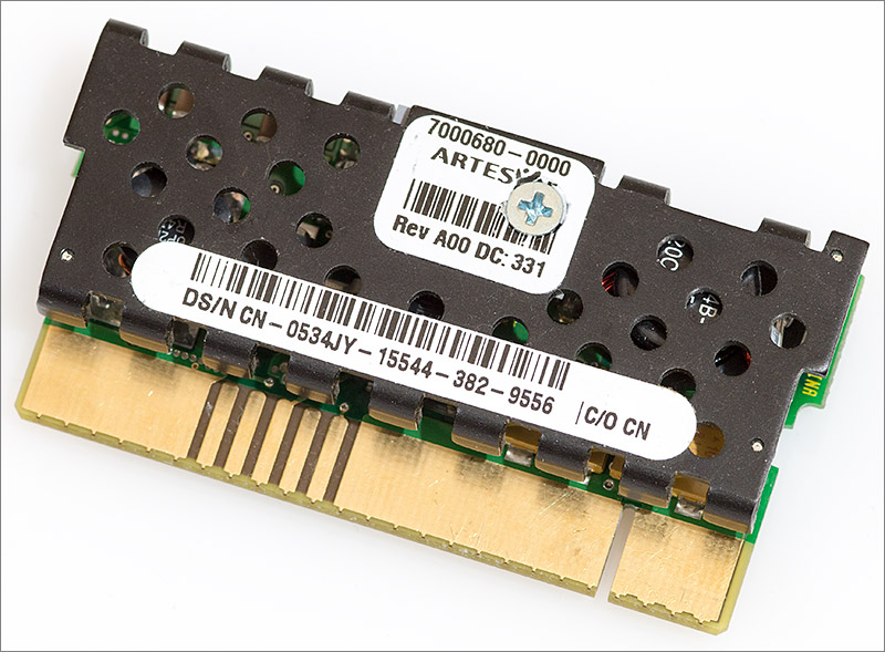
Some fairly aimless ebay fishing recently turned up a voltage regulator module for older Xeon CPUs. Initial thoughts of breaking it open for parts were quickly replaced by a desire to reverse-engineer it and perhaps reuse it as a miniature PSU board.


Click here to read about how I got on. A video, extensive load testing results and lots of photographs accompany the writeup.

When you get to the end of the article you'll note that there are many unanswered questions. If anyone knows what the unidentified pins do then please feel free to post your ideas. Eventually I'd like to build a board around this module and it would be nice to expose all the functionality.
77
If you're in any doubt about the correct wiring then I'd definitely recommend one of the cheap pre-made cables. If you do it yourself and you get it wrong then at best it won't work and at worst you'll damage the expensive motherboard beyond repair. If those adaptor cables had been available when I started my build then I would certainly have bought one.
78
Still active, yes. I'm still happily using my build with the same 2x X5680 and 48Gb RAM. It runs everything I throw at it and still remains responsive. The only dodgy part is the Windows 10 AMD drivers for the 7970. Sometimes rarely the driver stops responding and Windows resets it.

Quote
Is it possible to just rearrange the pins on my old PSU instead of cutting and resoldering

I'm afraid I don't understand this part. How do you re-arrange pins on a PSU? I've never seen one that allows you to reconfigure the pinout.

Quote
I can successfully insert my PCI-E 6 + 2 into the memory slot no problem, but I'm guessing the wire configuration is wrong

Yes definitely wrong, and also missing a 5V line. You're best off configuring that one from a molex connector like I did.

More importantly, do you know that the Z600 shares the same pinouts for the main board and memory power connectors as the Z800?
79
Quote from: Glen on September 09, 2016, 12:55:07 pm
It would seem as though the BTA312-600B is now discontinued, would the BTB616-600SWRG work as an equivelent?

If not, any suggestions?


Hi Glen, try the BTA12-600BWRG by ST Micro. It appears to be a direct replacement with the same 3Q triggering and current characteristics.

Google couldn't find the part number you quoted but I can guess from the code that it's a non-insulated (the tab is live) version with a more sensitive gate current (10mA). I prefer to use the insulated versions and while the 10mA gate variety will probably work I haven't tested it so couldn't say for sure.
80
I was going to give it a miss because it looks like just a single bug fix. But then you say it's critical so I'll probably install it at the weekend.
81
I'm now happily using Neon having upgraded from Kepler with no problems. After running Neon I accepted the option to upgrade the workspace. This left all the projects with a red 'x' over them because the GNU ARM Eclipse plugin needed upgrading. I went to the Eclipse Marketplace, selected the plugin and installed it. I removed all the offered debug options (JLink etc) except OpenOCD because that's the one I use.

Nothing needed changing to build the projects. They just worked.

To debug with OpenOCD I first had to update the 'Run/Debug -> OpenOCD' section in the main Eclipse preferences pages. My OpenOCD installation is 0.9.0 I set the 'Executable' field to 'openocd.exe' and the 'Folder' field to the full path of the 'bin-x64' folder that contains openocd.exe.

Then I created a new Run/Debug configuration for the 'blink' project. The type of the configuration was 'GDB OpenOCD Debugging'. On the 'Main' tab, 'Project' was correctly set to 'stm32plus-examples-blink'. In the 'C/C++ Application' field I entered the full path to the 'stm32plus-examples-blink.elf' output file.

On the 'Debugger' tab the only field I changed was the 'Config options' in which I entered '-f ../scripts/board/stm32f0discovery.cfg'. Modify the board file to match the one you are using. I was using my own F042 development board that is compatible for debugging with the STM32 F0 discovery. The other fields on that page were left as the defaults.

I was then able to run the debug session without having OpenOCD permanently running in a terminal behind Eclipse because the 'Start OpenOCD locally' option starts up the server and then tears it down after the debug session. This is nice.

One weird thing was that I was unable to set breakpoints at first - the 'Toggle breakpoint' option in the eclipse context menu was greyed out. This was fixed by selecting 'Breakpoints -> C/C++ Breakpoints' from the context menu that you get when you right-click in the breakpoints margin. It was initially set to 'default'.

Neon is a worthwhile upgrade. I like a dark 'zenburn' low contrast theme and in Neon they've managed to style virtually all the UI elements and at least some of the visual wastes of space (borders, frames etc) have gone. Only the main menu bar still looks wrong.
82
Hi Carlos,

I haven't got around to trying Neon for C++ projects yet, I'm still a way behind using Kepler. Have you tried using OpenOCD external to Eclipse as I described in my article?
83
stm32plus C++ library / Re: How to use GPIO pins?
August 03, 2016, 01:39:52 pm
Quote from: yaqwsx on August 03, 2016, 04:59:59 am
Thanks! GpioPinInitialiser is probably what I am looking for. I have one more question - when I am "user" and use the GpioX template, is it possible to have a multiple instances? Or is it meant as a singleton?


You can have as many instances as you like, even if they're identical types (ie. having same template parameters).

Quote
PS: My last question - when all instances of classes representing peripherals on a bus (eg. GPIO and Timers on AHB2) are destructed, is the bus clock disabled or not?


Not for GPIO. To achieve that reliably when a user could have multiple templates declared against the same GPIO port would require some tricky reference counting that would take up more space and use more cycles than it would be worth.

The other peripherals (adc/can/dac/spi/timer/usart etc....) do deactivate the peripheral clock when the destructor is called.
84
stm32plus C++ library / Re: How to use GPIO pins?
August 02, 2016, 02:27:44 pm
It sounds like you're using the library to create a higher level library of sorts. That means that you probably do not want the GpioA... etc templates because these are for when you are the 'user' and you want to configure a port to a known state. GpioPinRef is closely related to the port template and is used to pass around pins from the port. It's lightweight and can be passed around easily to general purpose methods because it's not a template. But it's not what you want.


  GpioB<DefaultDigitalInputFeature<6> > pb;
  GpioPinRef thePin=pb[6];


Quote
There is a pin map, which defines a structure for each pin. Could it be used in my program?


Yes. In my opinion that's the ideal way. If I were you I would create a template and parameterize it with a single type that's assumed to contain the user's selection of pins for your peripheral.

A good example is how I did the Ethernet MAC peripheral. Have your user create a type that defines the pins required by your peripheral using typedefs. Like this example for the MAC.

Now your template needs to receive the users type as a parameter. You know that each one of your pins is in that type as a typedef and so you can initialize them in your code. Here's the initializer for the ethernet MAC.
85
gcc is now following a few separate release tracks including 4.9.x, 5.x and 6.x and I thought it might be helpful to document which is the most recent supported version for stm32plus.

4.9.x: legacy. stm32plus was developed on the 4.9.x compilers and will likely continue to work on it for some time but you are encouraged to upgrade.

5.x: current. 5-2015-q4-major release from the 5.0 series released 2015-12-23 is the latest tested release. This is gcc version 5.2.1. Do not upgrade to the 5.4 release because it contains regression bugs that affect the build. 5.4.1 (5-2016-q3-update) is now supported. A workaround is in place for the regression.

6.x: future. No support yet but when an official release appears I will look to upgrade and test with this new release.
86
stm32plus C++ library / stm32plus 4.0.4 released
July 17, 2016, 07:00:03 am
The latest release of stm32plus is now 4.0.4 and you can get it from github.


87
No I don't bake my IC's. I do keep FPGAs and MCUs in a ziplock bag with a humidity card and some desiccant bags though.
88
It's hardware project time again. This time I've got around to tackling a rather large FPGA that I got hold of an ebay some time ago. Check out the article to see how I get on.

89
General discussion / Re: Cheap PCB production
July 05, 2016, 12:47:03 pm
Nice one Phil. It's a very satisfying moment when you apply power and it works.
90
General discussion / Re: Cheap PCB production
June 25, 2016, 02:48:53 am
Quote from: Phil on June 24, 2016, 05:23:49 pm
You are right. C3 was originally also a SMC, but I changed it at the last minute to THT as I didn't have the right SMC capacitor on hand but had loads of THT ones. I didn't care too much about the closeness as I will bend the capacitor over to the right.

Having tried surface mount aluminium electrolytics I now avoid them when using a reflow oven because they can end up looking like this. Apparently it doesn't affect their performance which I find to be quite surprising. Nevertheless I err on the side of caution and use either through-hole electrolytic or tantalum for the larger size capacitors now.

Quote
Thanks for your feedback, I'll send you a copy of the board :)

Thanks, you might have to tell me what it does though :)