


Building the phototrap. Part 1: Design.
Welcome to the first in a series of posts where I will document the design and build of a microcontroller based camera/flash phototrap that can support multiple sensors and multiple cameras and flashes.
The problem
As many of you are aware I have a keen interest in bird photography, particularly small song birds. My website contains many photographs of these birds in a perched environment and while I’m happy with the results that I get I have often thought about what it would take to photograph these fast moving small objects in-flight.
The answer to that question that doesn’t need any additional equipment is to use the camera’s high-speed ‘motor drive’ mode and hope that the 110ms repeat rate of my 1D Mark 2 is quick enough to capture the bird with the wings in the desired position fully in the frame. Depending on random chance like that is a tough task and may never yield the perfect shot.
The answer I’m looking for lies in a ‘phototrap’. A phototrap combines at least one sensor with a box that uses the input from the sensor to trigger a camera or a flash using the camera’s remote shutter port. So off I went, googling around to see what prior-art there was out there that I could either buy or build. This is what I found.
www.phototrap.com
This is the main commercial offering out there today. Its advantage is that it’s tried and tested in the field so I know that it would work, plus I could order one and have it with me in fairly short order. The disadvantages are that it’s expensive at over $500 delivered and it’s limited to the two IR beam sensors that it come with. Moreover, I can’t build it so no fun there!
An arduino trigger
This is the one that got me thinking that I could do it myself. The article clearly proves that a microcontroller based phototrap that supports configurable sensors was feasible. I decided that the ‘camera axe’ method was the way to go, only there was no fun involved for me in just following someone else’s plans so I’d do it all myself from scratch.
“If a job is worth doing, it’s worth doing well”
I sat down and sketched out the requirements for what I would consider the perfect phototrap to be capable of, and this is what I came up with.
- Multiple sensor inputs.
- Arbitrary sensor types.
- Multiple camera and/or flash outputs.
- Computer controlled triggering sequences.
- User interface with joystick, buttons and LCD screen.
- Persistent memory of all user settings
- Battery life of at least a full day.
- Must be buildable on stripboard.
- Must look cool. No ugly hacks allowed!
The control unit design
Now we have the requirements, let’s harden them into a real design with real components and circuit diagrams.
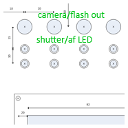
The control unit panel layout
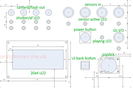
I created the above panel layout diagram using the Microsoft Visio drawing package. Draft measurements for the sizes and positions of the cutting are included. Shaded blue areas represent cutouts. Additional bounded areas around the cutouts indicate space occupied by a component underneath the panel face.
The 4 general purpose sensor inputs are located at the top right of the panel with the fifth i2c/high speed socket just below. The camera/flash outputs are at the top left. This layout allows for efficient cable routing away from the unit so that the UI controls are not obstructed.
The LCD is down the bottom left and the UI controls are next to it. This layout allows the user to control the unit with one hand away from the cables and leaving the screen unobstructed at all times.
The microcontroller
For the microcontroller we’ll use an Atmel ATmega1280. This comes in a package designed for surface-mounting on a PCB so we’ll use a board that already has the MCU on it. That board will be the Arduino Mega. Clones of the official mega board are available on ebay for as little as £25 at the time of writing so the price is right. This will be the most expensive component in the project by some margin.
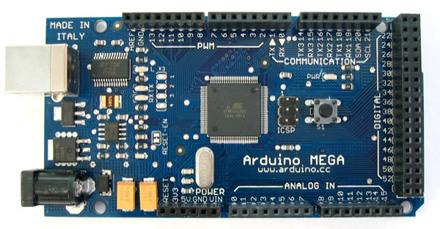
The Arduino Mega doesn’t expose all the GPIO pins available on the ATmega1280 but it does provide 54 digital and 16 analog pins. That will be more than enough for our needs.
The 16Mhz MCU itself comes with a healthy 128K of program memory. This will come in handy as I’m expecting the features provided by my control program to easily exceed the memory provided by the lower end ATmel MCUs.
The sensor sockets
We’re going to provide four sensor inputs and one additional I/O port wired to the I2C pins on the MCU for future expansion. These pins also have the advantage of being able to trigger interrupts so I have the option for an ultra-high-speed response input should I require it – most scenarios in nature photography will not need this and the response time is dominated by the camera’s shutter lag anyway. I decided to use the same 4-pin mini-DIN connector found on S-Video cables for the following reasons:
- They stay plugged in and don’t fall out at any angle.
- They don’t take up much space on the panel.
- Cables are cheap and easy to find.
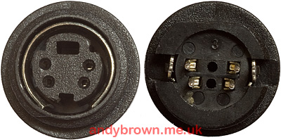
The 4 connectors on the back proved fiddly to solder but were not too bad. The trick is to solder all the wires you need before you fix the connectors into the panel. 🙂 The two outer pins that you can see are wired to the metal shield that you can see on the front view. I did not wire these to anything.
You should be able to find these sockets at any of the major electronics stores; CPC and mouser both have them. I bought mine from CPC in the UK in packs of 2 for about £1 per pack. I was pleased to find them available in a panel mount with a black front finish because I’d already decided that my unit was going to be finished in matte black.
The camera/flash sockets
The Canon cameras that I own use two different types of socket for remote triggering depending on the model. The high end 1-series cameras use a bizarre proprietary ‘N3’ connector that nobody sells separately. The low end rebel series use the much more common 2.5mm 3-pole TRS connector (a.k.a. stereo jack socket).
I decided to go with the 2.5mm 3-pole TRS connector for the camera/flash connectors because they are widely and cheaply available. I can buy a 5 metre cable on ebay for a few pounds and use it with no modifications on the rebel series cameras. Making a cable for the 1-series with their N3 connectors involves some hacking which I’ll cover in a future article.
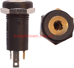
Again, these are trivial connectors to find at the major electronics stores. I got mine from CPC for about 60 pence for a pack of two. I took care to select black connectors to stay colour co-ordinated with the rest of the design.
The LCD
When it came to choosing the LCD there was certainly no shortage of choice. Character or graphical? Which backlight colour? What resolution to go for?
My design calls for a display that can be updated extremely quickly – it’s no use having a pretty graphical display if the MCU is spending its time maintaining a costly frame buffer when it should be checking for triggered sensors. At the same time, I have a requirement to make this device look cool so I chose a 4×20 character LCD with a blue backlight. Four lines exactly matches the number of sensor inputs in my design so I’ll be able to show a good UI.
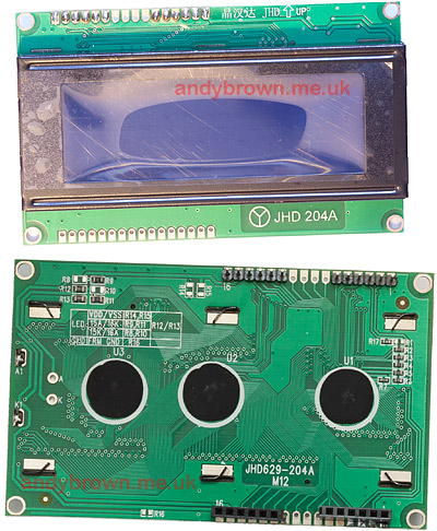
These LCDs are commonly available on ebay. Make sure you buy one that states that it is compatible with the HD44780 controller – that shouldn’t be difficult, just about all of them are. I paid about £7 from a seller in Hong Kong and had to wait about 3 weeks for delivery.
When choosing an LCD do note where they’ve put the row of holes on the PCB. Most of them only have one row located at the top or the bottom of the board. The one I chose allows for maximum flexibility by having holes at the top and bottom. In my design I will keep things tidy by running wires from the bottom set of holes to the MCU while using the top set to connect together holes that perform the same function. If I had bought an LCD with holes only in one place then the wires would have not have been as tidy inside the box.
It’s one thing finding a suitable LCD, that’s easy. The hard part is finding a panel-mounting bezel to fit. For reasons unknown these things are as rare as the proverbial hens teeth and without a bezel your project is going to look like a total hack! After days of searching I found a supplier in America who makes them for a reasonable price and was willing to ship to the UK.
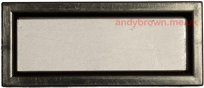
Dave at www.dhmicro.com was pleasant and easy to deal with and the bezels were priced at a very reasonable US$3.50 so I bought four so I’d have some in stock for future projects. The picture above shows the bezel with its protective plastic strip covering the window.
The power supply
Our requirement is to have a system that will run for an entire day on battery power. We have some flexibility around the voltage because the typical 5V voltage regulator that we will use to provide power to the system accepts a wide range of input voltages. In practice this means batteries of 8.4V, 9V and 12V were all in the frame.
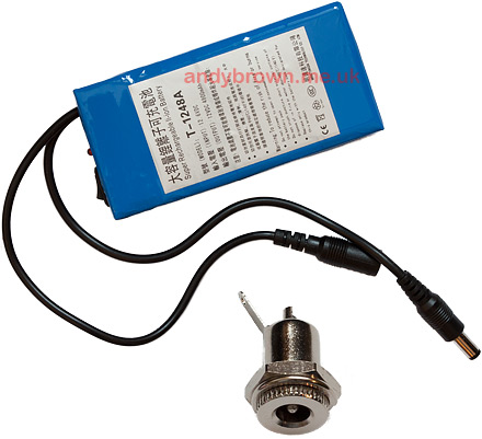
The battery I chose is shown in the image above. It’s advertised on ebay as a 12V 4800mAh pack, costs about £16 and it comes with a very useful 2.1mm DC plug on the end (the other connector is for charging) and also an on/off rocker switch on the end. Like many batteries advertised on ebay I suspect the capacity of 4800mAh to be overstated. I haven’t done a proper capacity test but I did feel that it recharged from empty to full rather too quickly to be a 4800mAh unit. However, during my testing and prototyping it took a few months to discharge therefore it easily satisfies my requirement and I’m happy with it.
The 2.1mm socket that you can see in the image is available from all electronics stores. I got mine from CPC for 58 pence. This socket will be mounted down the side of the enclosure.
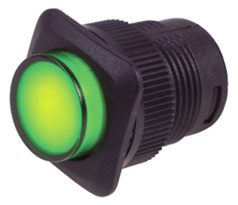
The above image shows the SPST locking illuminated power button that is mounted on the front panel – except that the one I bought has a blue LED instead of green so that it matches the colour of the LCD. It cost me £2.59 from Maplin in the UK. When buying this switch make sure that it has four terminals on the back, two are for the switch and the other two are for the built-in LED. The web is awash with 12V illuminated neon switches designed for automotive applications and you don’t want those.
The LEDs
The front panel sports a total of 14 indicator LEDs in red, amber and green. I’ve used 3mm LEDs throughout and I bought them on ebay from a Hong Kong seller. It cost about £3 for 100 and he even included a hundred 470R resistors for free. Bargain!
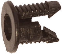
LEDs cannot be panel mounted without some kind of holding bezel. I searched around and found a set of 50 black plastic clip bezels of the type shown in the image above for £2.50 on ebay. These holders will allow the LEDs to be mounted almost flush with the panel and they are the right colour for my design.
The joystick
Our user interface is designed to be navigable using only a joystick for directional controls, a button for affirmation and a button for ‘back’. This is a reasonable approximation to the way that users are familiar with when web browsing – they use the mouse to point, the mouse button to click and they use the browser’s back button to go backwards.
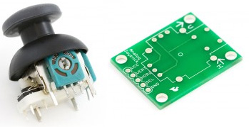
The joystick that we are going to use is the Playstation 2 joystick sold by Sparkfun. It is an analogue joystick that reports a value proportional to how far it is pushed, and it also has a built-in button – you press the joystick down to activate it. To save us some work Sparkfun have produced a useful breakout board that you can see in the above picture. Not only does it provide easy to access solder points for the joystick functions but it also provides 4 screw holes that we can use to mount the joystick to our front panel.
Sparkfun products are sold by many retailers worldwide. You should be able to find the joystick and board easily and the total cost should be around £5.
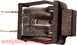
There are no special requirements for the back button (above). It just needs to be a small SPST momentary switch. The image above shows the one that I chose. It cost about 30 pence from an online retailer. With hindsight I should probably have spent a little more to get one with a higher quality ‘feel’ to it.
The USB connector
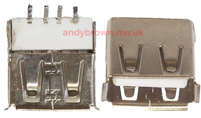
I decided to fit a type ‘A’ USB connector to the side of the box next to the power socket. This allows me to continue to update the program firmware after the project is assembled and the box closed. It’s possible to buy panel-mount USB connectors. They cost about £4 and I did buy one to evaluate it. Unfortunately they are physically rather large so instead I decided to use a connector that’s designed for PCB mounting, however we won’t be mounting it to any PCB – we’ll fix it into the side of our case.
I scavenged the connector in the picture from a broken USB hub so it cost me nothing. I note that you can get them from CPC for about 40 pence.
The buzzer
Including a piezo buzzer in the control unit will allow us to set up and test the unit in the field prior to live operation. The operating system will permit the sensors to be tested using audible feedback through the buzzer.
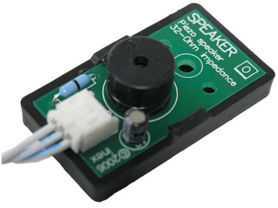
The buzzer that I purchased is the one illustrated above, “Inex Piezo Speaker Module”. I got it from Active Robots in the UK for £3.45. Any 3-wire piezo speaker will do the job, it just needs to be triggerable by a 5V logic high.
The enclosure and case
Buying a good looking enclosure should be easier and cheaper than this! Nothing stocked as an official ‘project box’ by the electronics stores was the right size or shape. I even considered contracting out the front panel to Schaeffer AG, a company who specialise in cutting custom front panels.
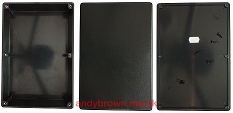
In the end it was ebay to the rescue again. I found an ABS plastic box sold by allendale-stores, measuring 220 x 151 x 96mm. This was just about perfect for my needs and cost only £6.70 delivered.
My vision for the full system involves taking the completed box and mounting it inside a pick-and-pluck foam case together with the external battery, the sensors required for the day and any cabling.
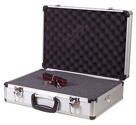
This is the case that I bought from Maplin in the UK. It’s described as ‘Flight case with foam’. At the time it cost me £20 which I thought was very reasonable until I just checked now and saw that it’s on offer for £15! The foam inside the case is divided into loosely connected 10mm cubes that can easily be cut out to create custom voids for the equipment.
The sensors
My design allows for any sensors to be plugged in to the unit so long as the operating system knows how to recognise and act upon their signals. I’ll cover the design and build of each of the following types of sensor in forthcoming posts.
- Pulsed and modulated high-power infra-red beam.
- X-Band radar motion detector.
- PIR infra-red motion detector.
- Lightning trigger.
- Ultrasonic trigger.
- Sonic trigger.
- Laser trigger.
Article series index
Use the following links to navigate through this series of articles.
| Part 1: Design | You are here. |
| Part 2: The control unit electronics | |
| Part 3: Control unit assembly | |
| Part 4: The operating system | Coming soon! |
| Part 5: The infra-red beam sensor | |
| Part 6: The X-band radar sensor | Coming soon! |
| Part 7: The PIR infra-red sensor | Coming soon! |
| Part 8: The lightning trigger | Coming soon! |
| Part 9: The ultrasonic trigger | Coming soon! |
| Part 10: The sonic trigger | Coming soon! |
| Part 11: The laser trigger | Coming soon! |