


How to hand solder an LCD FPC/FFC connector
Let’s face it, full-colour TFT displays are cool and adding one to your project is going to instantly endow your project with coolness. The problem for the hobbyist is that they come with flexible flat connectors known as FPC or FFC connectors. These are designed to be soldered to a PCB using a ‘hot-bar’ device that is pressed across all the terminals at once, instantly soldering them to the board. Nice if you’ve got one.
Help is at hand. There are many suppliers on ebay that will sell you a small TFT already mated to a PCB with the FPC connector broken out into a 2.54mm DIP header. If these satisfy your needs then buy them, you’ll be saving yourself a whole lot of work.
But what if the panel you want only comes ‘naked’, or perhaps you want to drive the signals directly as you’ll have to do if you want to stream video to it. If you fall into these categories then you are going to have to tackle the FPC connector yourself, and I’m going to show you how.
Parts list
- A TFT LCD with an FPC connector.
- A PCB to solder it to.
- Soldering iron with 1mm or smaller bit.
- Electrical insulation tape.
- Solder, flux and solder wick.
- Powerful magnifying glass or stereo microscope.
Although you can get away with a good magnifying glass on a stand I strongly recommend that you invest in a 20x stereo microscope. Using one of these has been a revelation for me. It really makes working with tiny components a walk in the park.
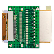
The LCD and adaptor board
The TFT LCD I am going use is a 3.5″ unit from ebay seller electronics-lee that came with a breakout board. I’m happy to recommend electronics-lee as I’ve had several items from him and all have arrived very quickly and been well priced.
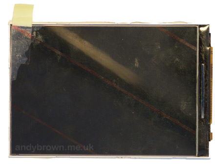
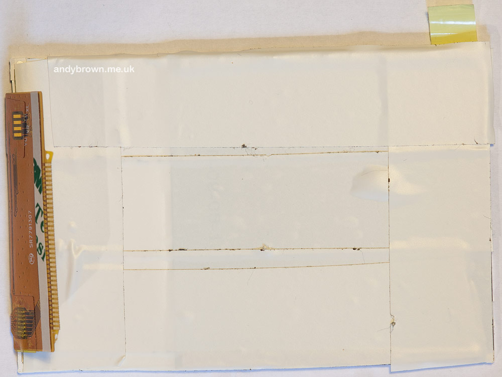
A plastic film protects the screen from damage.
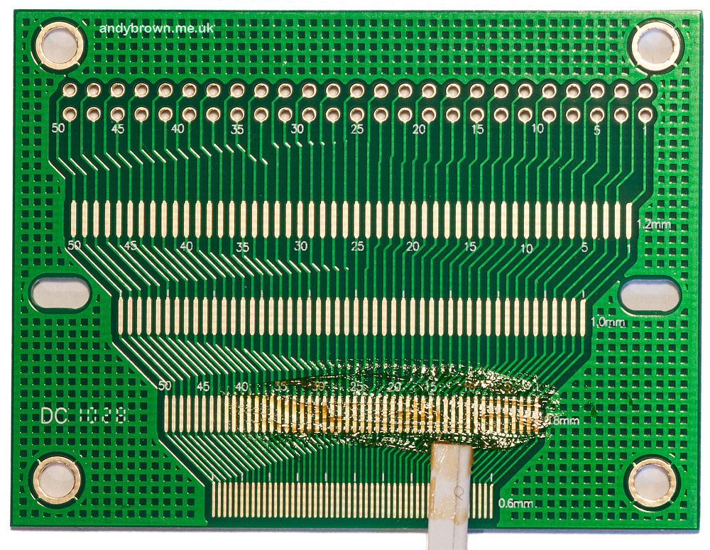
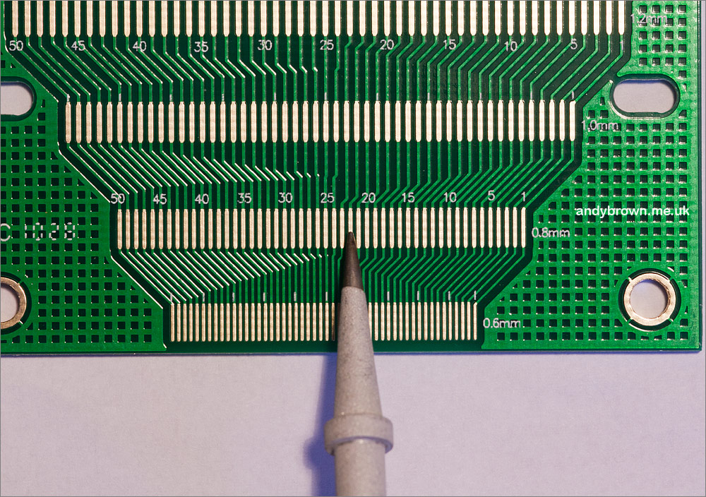
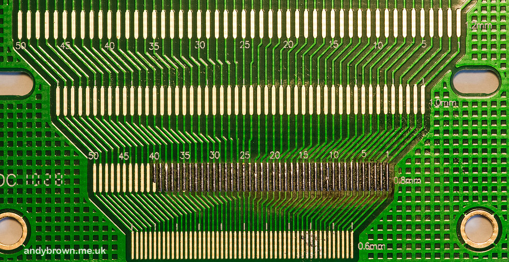
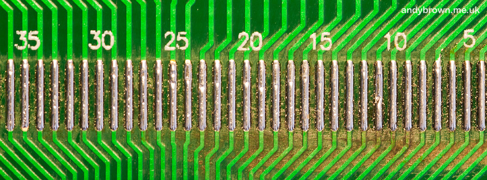
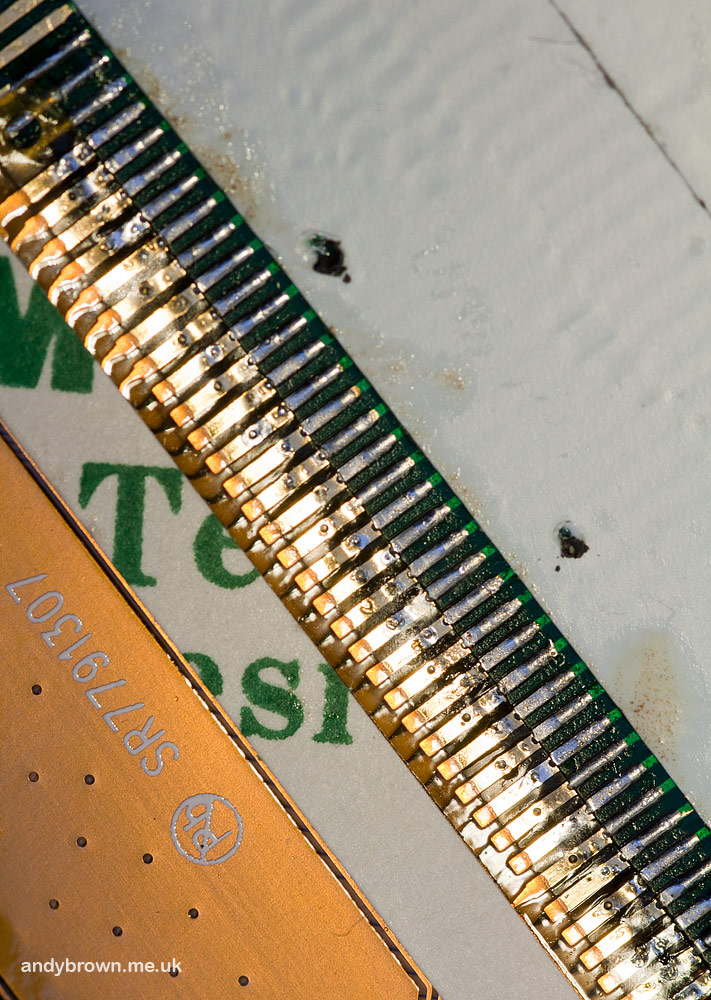
The breakout board is suitable for many different FPC pin pitches. By holding the FPC connector up against the board I can see that mine has a 0.8mm pitch and 37 terminals. As a bonus I can see that each terminal has a very small hole punched in it. This hole is designed to allow solder to flow up from underneath, making a better connection.

The FPC terminals have a 0.8mm pitch. Click for larger.
We are going to use a reflow technique to solder this connector. The idea is that we lay down solder on to the board pads and then reflow it to create the connection. I was surprised how easy this was.
Step 1: Flux the board
Make yourself a spatula from some folded paper and use it to spread flux as evenly as you can across all the pads that you’re going to use.
All fluxed up. Click for larger.
Step 2: Solder the pads
You can do this with a standard size soldering bit since we’re going to be using the side of the bit, not the tip. However I’m going to fit my 1mm bit and use that because I’m going to need it later and I don’t want to change it.
A 1mm soldering iron bit. Click for larger.
Melt a decent blob of solder on to your iron and hold it such that the side of the bit will come into contact with the pads. Now drag your iron across all the pads in an even motion that should take about 3 seconds to go from side to side.
The trick here is that the solder is attracted to the pads and repelled by the board in between. Examine the results and if any of the pads have been missed then drag the iron over again until you’re happy.
Tinned pads. Click for larger.
Use your magnifier or microscope to inspect for solder bridges between pads. If there are any then wick up the solder bridge. There were no solder bridges when I did it so I did not need to do any remedial wicking.
A close-up view. Click for larger.
Now clean up the molten flux with some Isopropyl Alcohol (IPA). IPA is cheaply available in small bottles sold as camera lens cleaning fluid.
Take a rest, you’re half-way there!
Step 3: Preparing the board
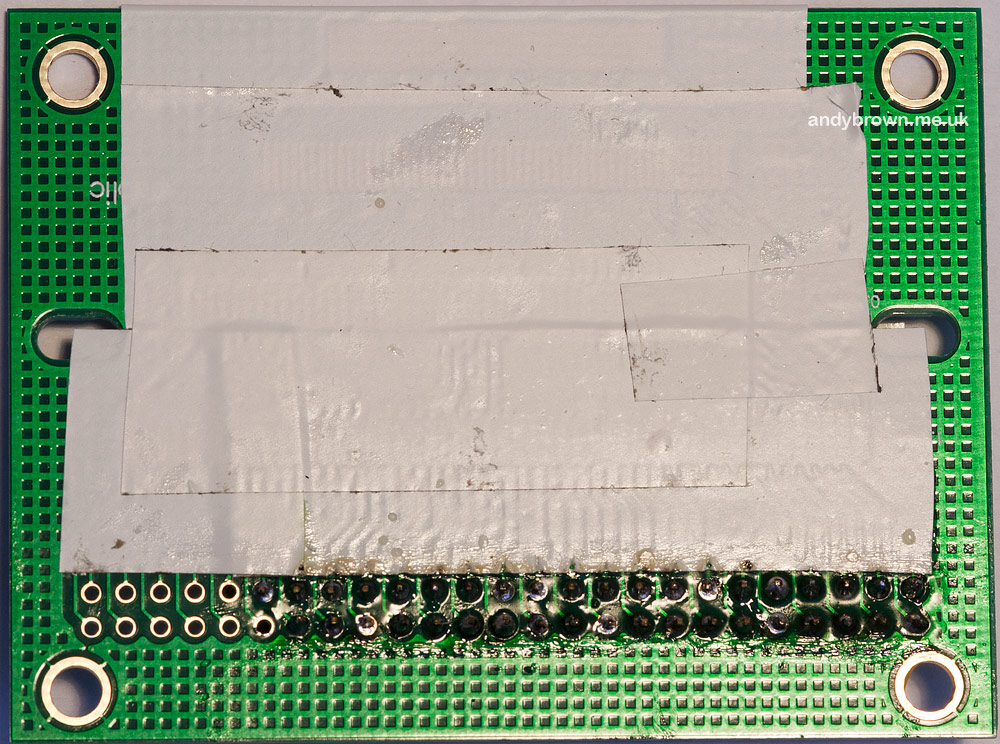
I need to mask off the traces on the board that I’m not going to use so that they won’t create short-circuits during operation. I use electrical insulation tape to do that.
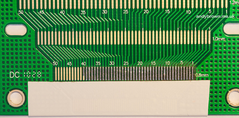
Masked off pads. Click for larger.
Fully masked. Click for larger.
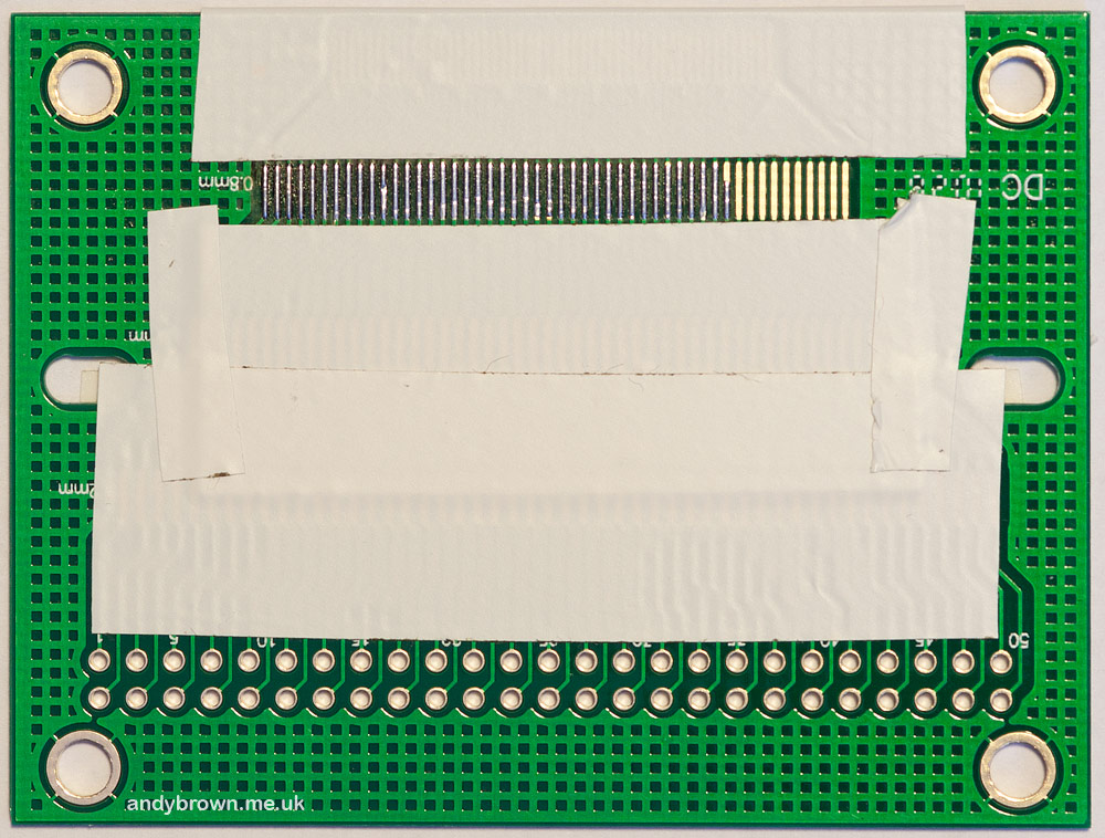
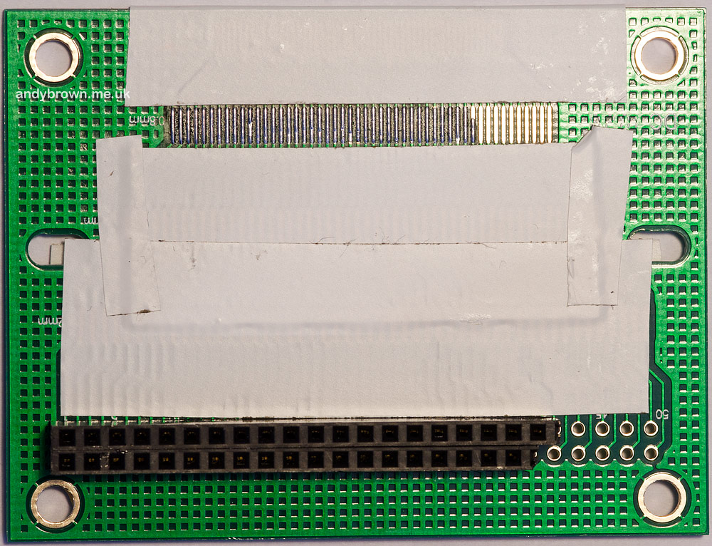
This adaptor board has traces on the flip side that need to be masked off.

The flip side. Click for larger.
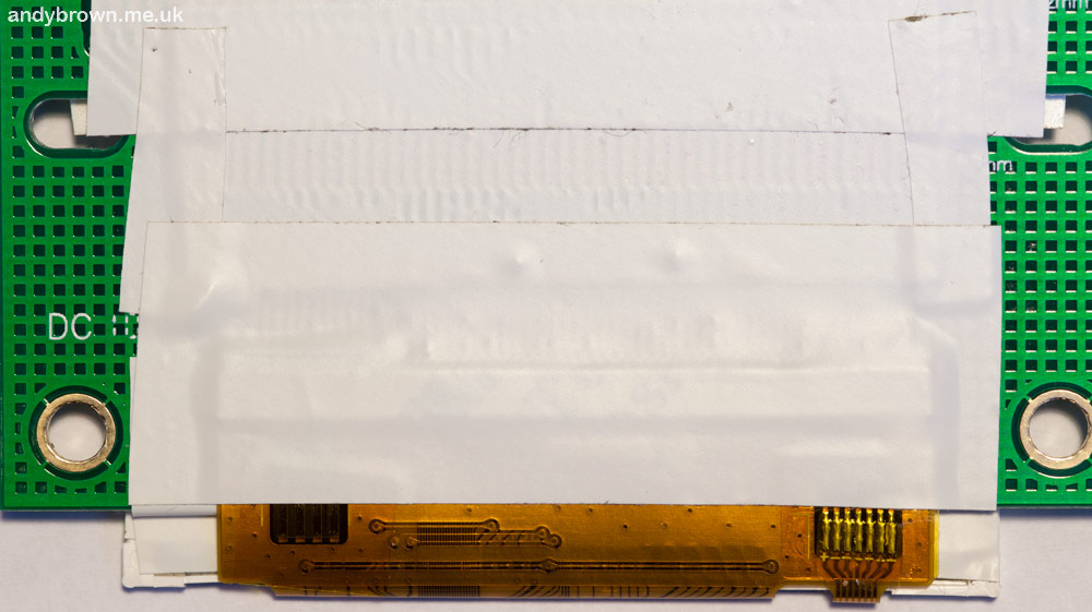
The last thing to get the masking treatment is the aluminium underside of the TFT panel.
Masking the panel back. Click for larger.
Step 4: Solder the DIP header
Now is a great time to solder the DIP header into place because you’re not going to be able to get to it easily after the FPC connector has been soldered down.
The back-side of the DIP header. Click for larger.
You can either buy a DIP header that suits your size requirements or you can cement your reputation as a backroom hacker by cutting a pair of SIP headers to size and supergluing them together to make a DIP! No prizes for guessing what I did…
The front of the DIP header. Click for larger.
Step 5: Soldering the FPC
Now the fun part. This need not be difficult and you can greatly increase your chances of success by preparing well.
You are going to need to do this under a microscope or powerful magnifier. The microscope will have built-in illumination, if you are working with a magnifier then ensure that you have your work area under a bright light.
We need to find a way of totally eliminating the natural shaking that the human body will transmit through the soldering iron, and do so with 100% repeatability as you work on each terminal. Here’s how.
Find a metal bar that you can use to rest the hot part of the iron on without setting fire to anything. With the hot part of the iron resting on the bar practice pivoting the iron over it so that the bit can be brought down on to each terminal. This method completely eliminates your body’s natural shake allowing you to work as accurately as if you were a robot. Believe me, my preparation for this operation consisted of a night-before of beer and curry followed by three cups of fully caffeinated black tea in the morning right before I started this and I had a 100% success rate using this technique.
Before starting on the FPC connector make sure you paste a thin layer of flux over the tinned board connectors. This will help the solder to reflow smoothly over the FPC terminals.
Working under the microscope or magnifier, carefully align the FPC connector with the tinned pads ensuring that it’s straight and that each terminal is completely overlapping the pad. Don’t overlap the pad more than the terminal length because there may be some traces further back on the connector that could cause a short circuit. Hold it down like that with one of your hands.
Now with your soldering iron in the other hand with a clean bit with no solder on it pivot over your metal bar until you are pressing down on the first terminal. The solder below the terminal will melt and bubble up through the tiny hole in the terminal. Lift the iron and let it set. Do the same for the terminal at the other end of the connector.
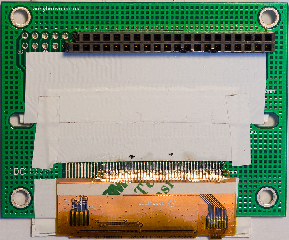
All done. Click for larger.
Now you can just repeat the process for every pin along the connector. When you’re done go back and check each terminal, repeating the pressing down with the iron process for any terminal that is still sitting up above the board – there will always be one or two like this.
A close up. Click for larger.
Step 6: Tape it down
The terminals that you have just soldered are quite delicate and if allowed to flex then they can easily snap off. Our final step then is to tape down the joint so it cannot flex and break.
Cut off a strip of insulation tape and apply it over the connections.
Securely taped down. Click for larger.
Finished!
Hopefully this guide has helped you overcome any doubts you had about being able to hand-solder these delicate connectors. It’s really not that hard as long as you prepare well.
Click here to see the hand-soldered panel in action. As you can see it works perfectly.