Filtering the 5V USB power supply line

I’m currently working on a new project that contains sensitive analogue components and have rediscovered what many before me already know, that is that the VUSB 5V line that comes out from your computer’s USB hub is noisy. In fact I was surprised at just how noisy it is. There’s random noise at high and low frequencies. There’s persistent ripple and some mightily impressive spikes that sail through at seemingly random time intervals. If you’re running a sensitive component such as an ADC or DAC then you need a clean power supply and all this noise will really ruin your day.

Anyway I thought I’d provide a practical example of how to clean up the power supply and eliminate all that noise. The result is a nice and stable VBUS line that you can use to feed your sensitive circuits.


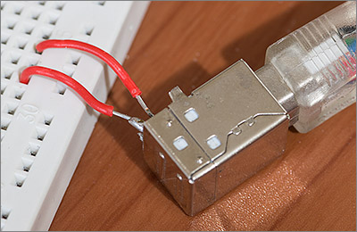
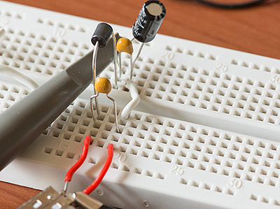
A hacked USB B connector

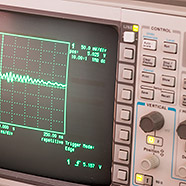
I’l be using the hacked USB B connector pictured above and connected to a breadboard for testing. I’ll be using my trusty old HP 500MHz oscilloscope and I’ll be probing directly at the component legs so as not to introduce noise from jumper wires. I should really be using a ground spring on the scope probe instead of a wire and clip but I haven’t got one those so I can’t.

Firstly let’s establish the baseline by probing VUSB on a couple of USB ports. I have a number of root hubs exposed through the front panel of my case. The two blue ports on the left connect to a generic no-name PCIe USB 3 expansion card. The remaining four ports connect back into the motherboard USB 2 headers.


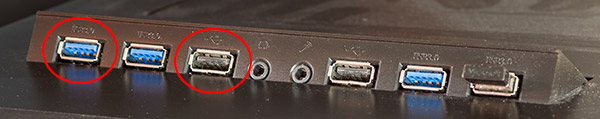
I’ll be testing the circled ports

For these tests I’ll be looking separately at VUSB on the USB 2 and 3 hubs on the left of the picture. The cables from the back of these ports has to travel quite a long way across the case to the motherboard header for the USB 2 ports and across the board to the slots for the USB 3 ports.

The unfiltered power supply

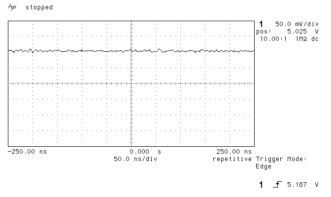
Let’s get started by showing just how bad things are without any filtering. Here’s a selection of screen grabs from the oscilloscope showing the noise on the supply from the two ports. The vertical resolution is 50mV/div in all the captures.

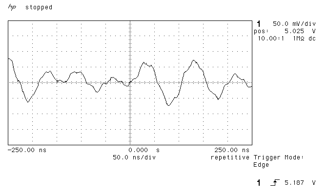
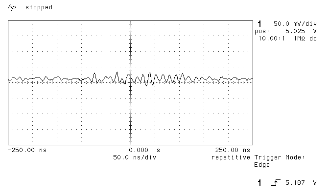
USB 2 unfiltered VBUS


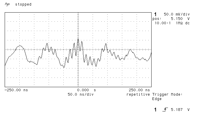
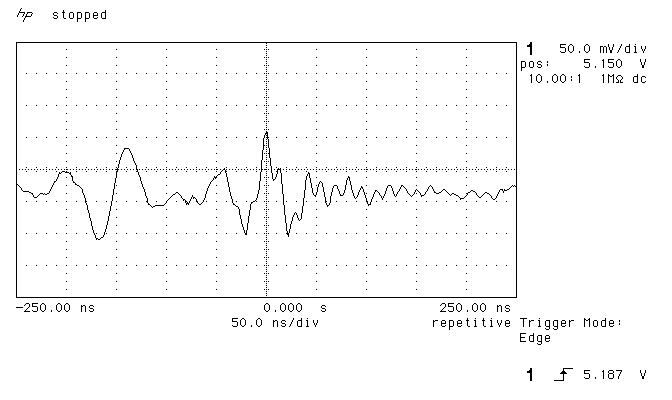
I’m sure you’ll agree the noise levels are pretty awful with spikes of +/- 100mV. I don’t think your sensitive analogue components would thank you for connecting them to this supply.

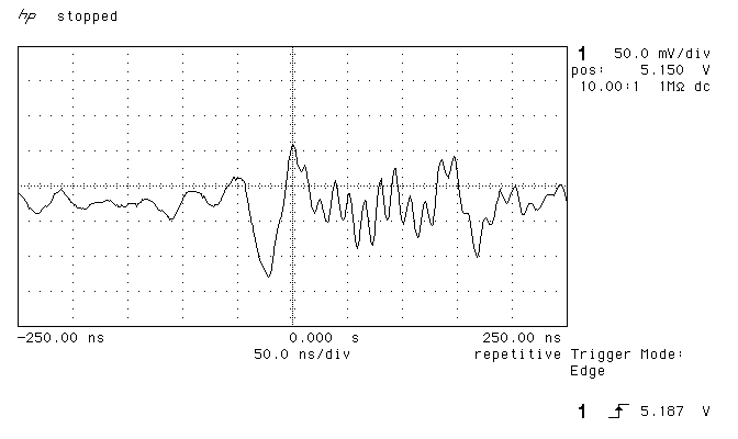
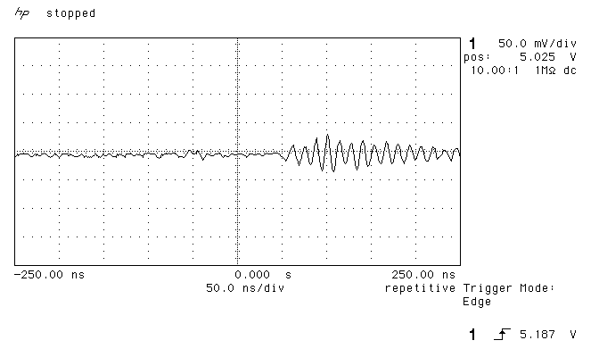
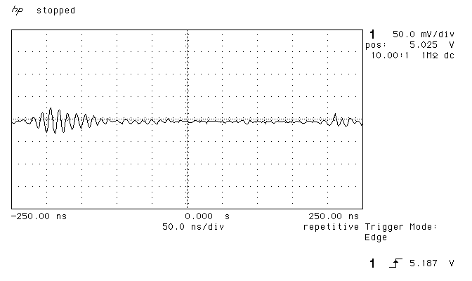
USB 3 unfiltered VBUS


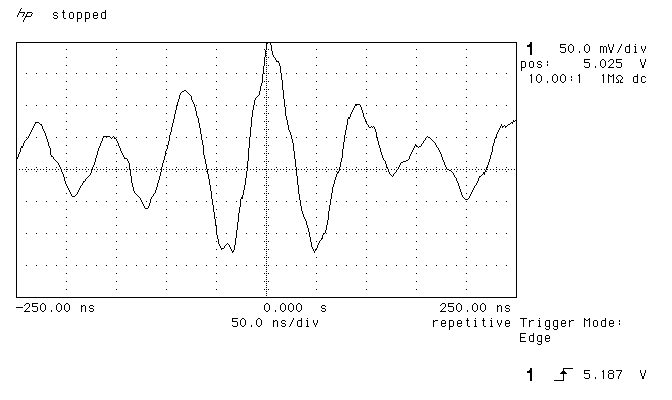
The noise on my USB 3 port is even worse than on the USB 2 port. I’ve got spikes, harmonics of spikes and even a pretty decent sine wave in there! Maybe it’s because the cable has to travel all the way across the motherboard or maybe it’s just because I bought a cheap USB 3 card.

Filtering the noise

I’m going to filter out the noise using a selection of capacitors and a ferrite bead based on the values provided in this FTDI application note and if any significant noise is still present then I’ll tweak the values of the components until it’s gone.

Here’s the schematic for the filter. It’s basically an LC filter with a selection of additional capacitors chosen to respond to different frequency ranges. It’s a little known fact that the USB 2.0 standard mandates a maximum of 10µF in parallel with VUSB to limit the inrush current. I’ll admit to having broken this rule several times in the past and the world didn’t end but do bear this in mind if you’re designing a product for mass production. If you do need significantly more capacitance than 10µF then the FTDI application note shows one way that you can design a slow start into your circuit to limit the inrush current.


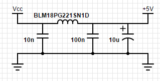
That’s the USB input on the left and the filtered output on the right

I have all of those components available in through-hole form. The long leads and the breadboard interconnects are not ideal from a noise point of view. All those exposed wires will probably act as tiny little antenna picking up stray noise from the environment.

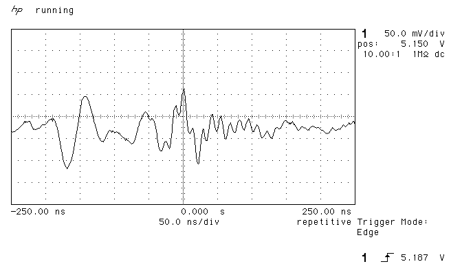
Now let’s take a look at how the power supply line has cleaned up with the filtering components in place. Firstly here’s how the USB 2 supply looks with filtering:
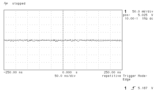
USB 2 filtered VBUS


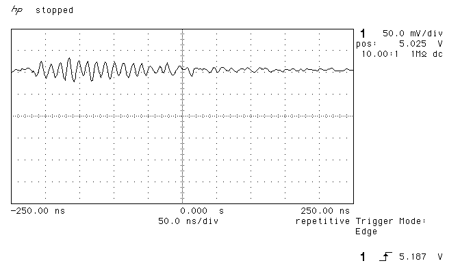
I’m sure you’ll agree that this is a huge improvement over the unfiltered supply. Noise is infrequent and limited to 50mV when it does occur.
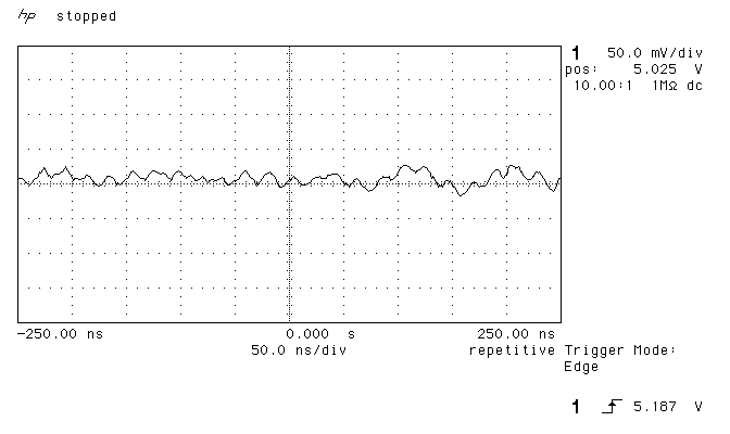
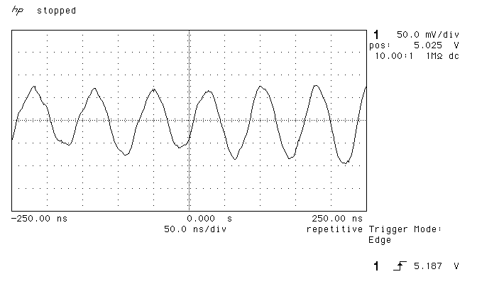
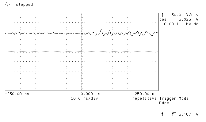
USB 3 filtered VBUS


Again you can see that the filter has done its job very well with noise levels about the same as for my USB 2 port. The noise patterns are also very similar which makes me think that maybe this residual noise is being picked up by the leads in my circuit.

Conclusion

The addition of a few small and cheap components can make a huge difference to the stability of the USB power supply. Noise is reduced to a low, tolerable level that should not present any issues for sensitive components.

I hope you enjoyed this short practical demonstration. If I’ve saved at least one of you from having to bin a batch of PCBs and do a redesign to filter supply noise then I’ll be happy.

  • Awesome blog! I have a Raspberry Pi connected to an LCD monitor, but the noise from the USB port is crazy. I can hear the screen brightness and the Raspberry Pi LED activity through the USB speakers (using the analog audio port). I wonder is this little circuit would solve this issue, because I know that it’s working like a charm if I connect the Raspberry Pi on another USB port or directly to the power socket in the wall instead of the monitor. However, I’ve never heard of “BLM18pg221sn1d” before. I’m new to electronics, but I have the other components lying around… Tried to find it on eBay, but couldn’t find it.. are there any alternative components that would do the same trick? I’ve also tried adding a ferrite core to the Raspberry Pi USB power cord without any positivt effect.

    • Hi, that part is a ferrite bead. You can try replacing it with a different part. Ferrites are characterised by their impedance at 100MHz. Ideally you’d plot your noisy line in a spectrum analyzer (or the FFT function on your scope) and design a filter that blocks out the noise that you observe. In practice for a hobbyist ferrites are so cheap that you may as well buy a selection and experiment with them to find out which one performs best for you.

    • Luis F Portilla Berlanga

      I have the same problem! (Pi connected to LCD) then crazy noise on the audio jack. Did you tried the circuit? Could you fix your audio problems?

  • John Marable

    Your article was clear and useful. Not having an o scope, I implemented your circuit using your values and ferrite bead: a14070400ux1079. It fixed a problem with an Arduino Uno powered weather station that I have been working on for months. USB noise was causing rain and wind speed triggers on digital GPIO pins. Now I have a quiet Pi 3 and no more phantom rain. Thanks for saving my project with a few cents worth of parts.

    • Hi John, glad I could help. It’s always nice to hear when someone’s got a project working.

  • Ctgt

    I ask, hope you can answer me, what if it is the oposite, the noise comes out from the port of the audio device and goes through usb of my computer causing all the screech sound. Can I do it just like that and will work fine or should I change anything?

  • Swampy

    I only found the “BLM18pg221sn1d” as SMD. I am an electronic beginner and I want a THT-one for my breadboard to test it. Can you suggest me an similar one in THT-build?

    • I’ve tested with the Laird 28L0138-10R-10 and found it to be a suitable replacement

  • Pui Ho Lam

    what is the pass band of this circuit? Have you tried a higher order circuit?
    most usb3 hubs use 12V power supply. Maybe the 5V regulator in the supply is not good enough?

  • Puzzled

    I’ve got a problem powering an mp3 player in the car from a USB socket while it’s playing (audio goes to an FM transmitter to the radio). It’s fine by battery but if I plug in the USB cable I get intermittent pulsing noises, like it’s negotiating power or something. I tried cutting the white/green data line on a spare lead, and the player indicates it’s charging and plays OK for a while but I still get the audio cutting out for a second here and there. Would it help to filter the remaining red/black wires with your circuit? Thanks

    • If it’s fine on battery then it sounds like you’ve got noise on the power line that’s even getting through and interfering with the FM transmitter. Yes, I would try filtering the power line.

  • MichaelT

    Hi Andy, very informative post. I am using a 16-bit ADC with a microcontroller (Arduino UNO) to make very sensitive voltage measurements, feeding data to a PC via USB. The ADC and microcontroller are powered from the USB 5 V line, which I know is not very clean.

    It appears I can implement your filtering solution by modifying a USB cable. Is this a sensible idea or not recommended? Or perhaps modify on the Arduino board itself?

    • Hi, with a device as sensitive as a 16-bit ADC I’d be tempted to forget USB power and run it off a battery pack fed into an ultra-low noise LDO. Is that feasible for you?

      • MichaelT

        My application involves sampling the ADC for 2-3 seconds at 1000 Hz, then shifting the data onto the PC where I do further processing, FT, etc. I don’t think there is an easy alternative to the USB. Suppose I were to add the filter and see if it makes an improvement, would be the place to add it be close to the VCC pin of the ADC, or near the USB socket of the Arduino UNO?

  • James Parsons

    Hi.. I want to build this. The ferrite bead part – is this the same as “high frequency ferrite choke” or “rf choke” i have in my electronic parts catalog? These parts are rated with an inductance value. If so which one? Thanks?

    • Yes those are alternative terms for the same thing. If they’re cheap enough then try a few and observe the suppression effect with a scope.

  • Vittorio Colzani

    Hallo, unfortunately I don’t have an oscilloscope. What inductance value could I choose?

    • Quite possibly. It depends on the nature of the interference you’re experiencing. They’re so cheap though it’s probably worth buying some anyway to see if they’ll do the job.

  • Luca Betty

    hi, i have a fm trasmitter circuit that require 5 volts. i use now 3×1.5 batteries, but i would like to power it via usb. the problem is that when there is no audio source from the radio tuned in the frequency i listen the noise from power supply to the transmitter circuit . could this circuit solve the problem? HOW TO SOLVE THE PROBLEM OF THE STEMS? THANKS

  • GD

    Hi Andy,
    just testing an SMD proto

  • GD

    Hi Andy,
    currently testing a quick and dirty SMD version using BLM18PG221SN1D. Looks awful but testing went quite well. Looking forward better reception for a SDR receiver powered by a switching 5v psu. Data wires are directly connected on the USB connector, VCC and GND go to 10nF big cap on the right. Shielding goes on the USB metal body. Receiver is directly connected on the USB port. Unfortunately I have no scope on site. Thanks for the article!
    https://uploads.disquscdn.com/images/46e409e9d0d087027678ead545b01ea3b57294fd627102aac0a13e70319ae60b.jpg

  • steve

    guess who found noise in my noise-cancelling headphone while charging from usb? Anyway, thank you Andy.

  • Minos Chatzidakis

    Is this a wireless usb adapter (wifi dongle) that you have plugged in the rightest usb port in the second photo? I’d suspect that for the random noise too..
    Super nice post!

    Would you have an opinion on the oscilloscopes found in aliexpress? I’ve never heard those brands before..

    • Hi Minos, yes the dongle on the far right is a dongle for a Microsoft wireless keyboard.

      Regarding scopes, I have an Owon DS7102V. It’s OK. It’s not the best but according to the Eevblog forums the version I have is worth the price. I also have an old HP 54520A which, despite the age, is miles better quality but lacks modern features and has a very low sample depth. There’s a wealth of knowledge about scopes in the Eevblog forums and that’s where I’d go for research if I wanted to buy one today.

  • Milan Lipowski

    Great article! Yes, USB has crazy noise. But I decided to get 5v from audio toroidal transformer over LDO stabilizer and several audio Nichicon capacitors.

  • Does this ferrite look OK? 90 Ohms @ 100MHz
    (part no. Bead /4-900R-YY)
    http://cdn-reichelt.de/documents/datenblatt/B400/LEADEDBEADS.pdf

  • BF3000

    Good one.
    I need to try this for my usb sound card.

    • BF3000

      Well, it works perfectly.

      • That’s great news. I include this filter circuit on every USB-powered design now. The components are cheap and it “just works”.

  • Max Boonzaayer

    Hey Puzzled, I know it’s 2 years later, but you need a Ground Loop Isolator, they’re chips on ebay, and look like snake oil. But I tried one out in my car for a constantly on power Bluetooth receiver for my car, worked a charm

  • Stefan

    Hi, nice article! I will implement in in future designs! Would a TVS diode require adjustment of the filter component values?