


stm32plus: ILI9481 TFT driver

|
The code presented in this article requires a minimum of version 3.0.0 of my stm32plus library. |
The TFT panel
The ILI9481 is a driver IC for 480×320 (HVGA) TFT panels. These panels are typically found in mobile phones (for example the iPhone 3G although the display in that phone probably does not have a controller) and other portable devices. HVGA panels contain double the number of pixels of the common 320×240 (QVGA) panels.
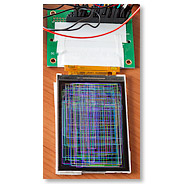
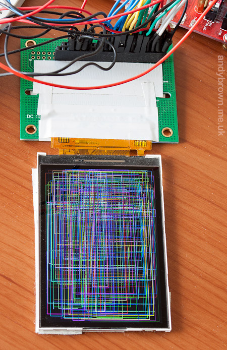
I picked up one of these panels on ebay. It didn’t come with a breakout board so I had to create one of my own.
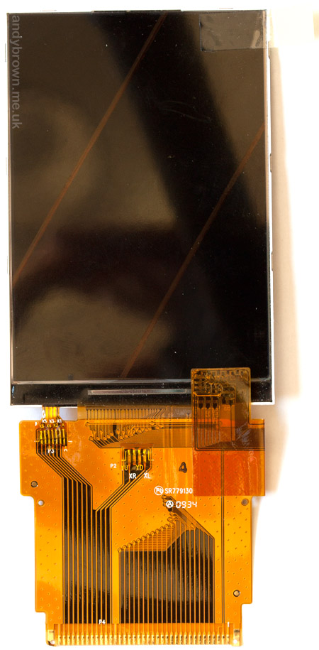
The bare 3.5″ panel with the FPC tail
I could have tried to track down a connector for the 37-pin, 0.5mm FPC connector but decided against it and just soldered the FPC directly to the adaptor board that the e-bay seller included with the display.
Pinout
The data sheet for the panel included the pinout. It’s a familiar 8080-style interface that is easily connected to the FSMC of the STM32 microcontroller.
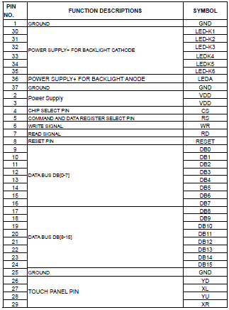
The pinout
The pins include the outputs from the resistive touch screen. It would be possible to create a breakout board that includes the popular ADS7843 to handle the decoding but I’m not going to do it here.
Backlight
The datasheet also included a schematic for the backlight. Since this is a relatively large 3.5″ panel it has a total of 6 white LEDs connected in parallel to act as a backlight.
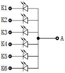
The backlight is a parallel LED array
Having the LEDs connected in parallel means that I can power them directly from a 3.3V supply without the need for a step-up DC-DC converter that would be required had the LEDs been connected in series.
Driving the LEDs at 20mA means that my voltage regulator is going to have supply 120mA to the backlight. It’s always worth double-checking your development board’s specification at times like these to ensure that the voltage regulator can cope.
If you’re creating a real application that has a backlight like this then you should be using a dedicated constant-current backlight controller. OnSemi have a good range to choose from. These devices all offer PWM control of their output as well as the basic function of providing a constant current to the LED array.
All hooked up and running the usual demo
My demo sequence exercises some of the common functions used in graphics operations such as rectangle, line and ellipse drawing as well as text rendering and hardware scrolling when the panel supports it (the ILI9481 does).
The ILI9481
The datasheet for the ILI9481 is readily available on the internet. It’s written to the high standard that I’ve come to expect from ILITek making the job of writing a driver really straightforward.
The panel supports 16 bit colour (5-6-5 format) and 18-bit colour (6-6-6 format). The STM32F103 can easily drive either colour format at a fast pace. I’ve come to realise that the observable difference between 64K and 262K colours is pretty low and generally I’ll use 64K for the extra speed that it offers.
![]()
Data transfer protocol for the 16-bit interface (click for larger)
Using a 16-bit interface we can transfer a 64K colour pixel in one operation. A 262K colour pixel costs an extra transfer per-pixel and therefore halves the speed just for those extra 2 bits.
STM32 wiring
Here’s the wiring mapping table that you’re going to need if you intend to hook one of these up to an STM32 MCU. You’re free to change the address line that you use for RS, the bank selector that you use for /CS and the GPIO pin for RESET.
| LCD signal | STM32 port | port function |
|---|---|---|
| D0 | PD14 | FSMC_D0 |
| D1 | PD15 | FSMC_D1 |
| D2 | PD0 | FSMC_D2 |
| D3 | PD1 | FSMC_D3 |
| D4 | PE7 | FSMC_D4 |
| D5 | PE8 | FSMC_D5 |
| D6 | PE9 | FSMC_D6 |
| D7 | PE10 | FSMC_D7 |
| D8 | PE11 | FSMC_D8 |
| D9 | PE12 | FSMC_D9 |
| D10 | PE13 | FSMC_D10 |
| D11 | PE14 | FSMC_D11 |
| D12 | PE15 | FSMC_D12 |
| D13 | PD8 | FSMC_D13 |
| D14 | PD9 | FSMC_D14 |
| D15 | PD10 | FSMC_D15 |
| /WR | PD5 | FSMC_nWE |
| /RD | PD4 | FSMC_nOE |
| /CS | PD7 | FSMC_nE1 |
| /RESET | PE1 | GPIO |
| RS (D/CX) | PD11 | FSMC_A16 |
stm32plus driver
stm32plus 2.0.0 comes with an updated ILI9481 demo application. Here’s an extract from the source code that shows how to set it up.
#include "config/stm32plus.h"
#include "config/display/tft.h"

using namespace stm32plus;
using namespace stm32plus::display;

class ILI9481Test {

  protected:
    typedef Fsmc16BitAccessMode<FsmcBank1NorSram1> LcdAccessMode;
    typedef ILI9481_Landscape_64K<LcdAccessMode> LcdPanel;

    LcdAccessMode *_accessMode;
    LcdPanel *_gl;
    Font *_font;

  public:
    void run() {

      // reset is on PE1 and RS (D/CX) is on PD11

      GpioE<DefaultDigitalOutputFeature<1> > pe;
      GpioD<DefaultFsmcAlternateFunctionFeature<11>> pd;

      // set up the FSMC with RS=A16 (PD11). The 60Mhz FSMC bus on the F4 needs
      // slower timings.

#if defined(STM32PLUS_F1)
      Fsmc8080LcdTiming fsmcTiming(0,2);
#else
      Fsmc8080LcdTiming fsmcTiming(2,10);
#endif

      _accessMode=new LcdAccessMode(fsmcTiming,16,pe[1]);

      // declare a panel

      _gl=new LcdPanel(*_accessMode);

      // apply gamma settings

      ILI9481Gamma gamma(0,0xf3,0,0xbc,0x50,0x1f,0,7,0x7f,0x7,0xf,0);
      _gl->applyGamma(gamma);

      // clear to black while the lights are out

      _gl->setBackground(0);
      _gl->clearScreen();

      // create the backlight on timer4, channel2 (PD13)

      DefaultBacklight backlight;

      // fade up to 100% in 4ms steps

      backlight.fadeTo(100,4);

      // create a font

      _font=new Font_VOLTER__28GOLDFISH_299;
      *_gl << *_font;
Let’s look at the code in a little more detail.
Includes and namespaces
#include "config/stm32plus.h"
#include "config/display/tft.h"

using namespace stm32plus;
using namespace stm32plus::display;
Firstly we need to include the headers that define the classes we’re going to use. Secondly, since all of stm32plus lives either in the stm32plus namespace or a sub-namespace (in this case stm32plus::display) we will import them into the global namespace to make the declarations of the objects less clumsy looking.
FSMC access mode and reset
    typedef Fsmc16BitAccessMode<FsmcBank1NorSram1> LcdAccessMode;
    typedef ILI9481_Landscape_64K<LcdAccessMode> LcdPanel;

    LcdAccessMode *_accessMode;
    LcdPanel *_gl;
    Font *_font;

  public:
    void run() {

      // reset is on PE1 and RS (D/CX) is on PD11

      GpioE<DefaultDigitalOutputFeature<1> > pe;
      GpioD<DefaultFsmcAlternateFunctionFeature<11>> pd;

      // set up the FSMC with RS=A16 (PD11). The 60Mhz FSMC bus on the F4 needs
      // slower timings.

#if defined(STM32PLUS_F1)
      Fsmc8080LcdTiming fsmcTiming(0,2);
#else
      Fsmc8080LcdTiming fsmcTiming(2,10);
#endif

      _accessMode=new LcdAccessMode(fsmcTiming,16,pe[1]);
We use an ‘access-mode’ class to control how we communicate with the panel. Here we initialise it to use the FSMC in 16-bit mode with A16 as the RS line (PD11). We will also be wiring up the panel’s RESET line to PE1.
We declare an Fsmc8080Lcdtiming object that takes care of the timing details. The two parameters are the address setup and data setup times in HCLK cycles. At full speed the STM32F1 has a 36MHz FSMC bus and the STM32F4 has a 60MHz bus. Therefore the timings may be different for each MCU if the bus is faster than the panel.
To determine the value of these parameters you need your panel’s data sheet and the equations in the ST Microelectronics application note AN2790 (google it). Alternatively you can just start with some large-ish numbers and decrease until the timings get too tight and the panel doesn’t respond!
Declare a panel
// declare a panel

_gl=new LcdPanel(*_accessMode);
Now that we have an access mode we can declare the panel. The constructor will ask the access mode class to reset the panel and then it will do the initialisation sequence.
Our example initialises it in landscape mode, 16 bit colour (64K). If you take a look at TftInterfaces.h you will see that following modes are available:
ILI9481_Portrait_64K
ILI9481_Landscape_64K
ILI9481_Portrait_262K
ILI9481_Landscape_262K
The predefined drivers are just C++ typedefs that bring together the necessary combination of template instantiations to create a coherent graphics library.
Gamma correction
      // apply gamma settings

      ILI9481Gamma gamma(0,0xf3,0,0xbc,0x50,0x1f,0,7,0x7f,0x7,0xf,0);
      _gl->applyGamma(gamma);
Gamma correction involves the manual adjustment of the panel’s response to different shades of grey to compensate for differences in the manufacturing process. Every panel will be slightly different.
Setting up the tweaks to the gamma curve are optional, a reasonable display will be obtained by using the default linear curve but if true-to-life colours are a requirement then a custom gamma curve is essential.
stm32plus includes an interactive gamma adjustment application, and that will be introduced in a future blog post. For now, you can just use the default settings and maybe come back to it later.
Backlight
// create the backlight on timer4, channel2 (PD13)

DefaultBacklight backlight;

// fade up to 100% in 4ms steps

backlight.fadeTo(100,4);
stm32plus comes with a PWM backlight controller template class, and a subclass of that called DefaultBacklight that assumes you can connect the backlight regulator to PD13.
This PWM output should be used to drive the base of suitable transistor, or the ‘enable’ pin of a constant current backlight driver. It should not be used to directly power the backlight because it’s likely to draw too much current from the MCU pin.
The fadeTo method allows smooth transitioning of the backlight between levels to give a pleasing user experience.
Font selection
// create a font

_font=new Font_VOLTER__28GOLDFISH_299;
*_gl << *_font;
stm32plus (as of 1.2.0) now supports the very convenient stream ‘<<' operator to output text and numbers to the display. To do this the operator needs to know which font to use, and we do that by using the << operator with the font object as the operand.
Get the source code
It’s all in stm32plus 2.0.0 (or later) available from my downloads page.
Watch the videos
I’ve uploaded a pair of short, out of focus and badly produced video that you can waste some of your valuable time by watching if you want to see the ILI9481 panel in action.
First the STM32F103. In the video I’m running the debug version of the code. The optimised build runs about 2.5x faster. For example, a full-screen clear takes 25ms when optimised and 65ms when in debug mode.
Secondly the STM32F4 Discovery board. This is running a build optimised for speed (-O3).