


stm32plus: HX8347A TFT driver

|
The code presented in this article requires a minimum of version 3.0.0 of my stm32plus library. |
The HX8347A controller
I have written a C++ driver for 320×240 (QVGA) TFT LCD panels that have an HX8347A controller built in to them. This driver is included with my open source stm32plus C++ library and this article will show you how to use it with the STM32F103* ARM Cortex M3 microcontroller family running at 72Mhz.
Updated sample code is available with stm32plus 2.0.0 or later and there’s a video hosted on YouTube that accompanies this article.
The Himax 8347A controller is a controller that is very typical of the genre. It supports 18-bit, 16-bit and serial (SPI) access. It has its own onboard GRAM frame-buffer and expects you to send it commands that read and write from that buffer.
In order to support a wide range of host panels the controller has a wide range of voltage and timing options that you have to get just right as part of the reset sequence.
The panel
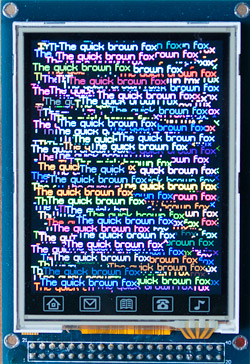
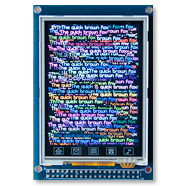
The text is a lot sharper than this. The camera creates a halo around the high-contrast colour transitions that results in a slightly fuzzy appearance.
Here’s the panel that I’ll be demonstrating. They are commonly available on ebay from Chinese sellers and come attached to their own breakout board. The breakout board has some advantages and some disadvantages. In its favour are:
- You don’t have to solder the FPC tail yourself. That’s just not fun.
- A touch screen IC is provided and broken out to the pin header. More on that in a future article.
- An SD cage is provided and the serial interface is broken out to the pin header.
- Backlight current-limiting circuitry is provided, you just need to supply 3.3V to the pin.
It’s not all roses however, the breakout board is lacking in some key areas.
- It’s hardwired for 64K colours on a 16-bit bus. If you want to try the 18-bit bus, the SPI interface, or run it at 262K colours then that’s tough. You can’t.
- The SDIO pins to the SD card are not available. Can’t really complain about this since the SD cage is really a freebie on the board.
Interfacing to the STM32
Here’s the connector pinout.
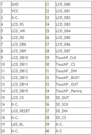
No surprises in the MCU interface. The 16 data lines are all there along with the usual read, write, register-select, chip-select and a reset line.
By far the most efficient way to attach this device to the MCU is to use the Flexible Static Memory Controller (FSMC) to make writing to the LCD as simple as writing a 16-bit value to a location in the FSMC’s range.
Furthermore, we can control the vital register-select (RS) line by wiring it to one of the FSMC’s data lines. That way we can choose whether we are writing to GRAM or writing to a register by the appropriate selection of a memory address that will activate the RS line.
| Memory address | A16 line | transfer |
|---|---|---|
| 0x6000 0000 | 0 | register select |
| 0x6002 0000 | 1 | GRAM data |
The above table shows what happens in my demo when I configure address line A16 to be attached to LCD RS. Note that the binary address indicated by the address lines (0x6000 0000 | 1<<16) is one power of two less than the memory address because we set the FSMC up to address in 16-bit mode.
stm32plus code
Naturally stm32plus abstracts away all the ugly stuff, and believe me setting up the FSMC is not a pretty sight. Here’s some sample code used to initialise the display.
class HX8347ATest {

  protected:
    typedef Fsmc16BitAccessMode<FsmcBank1NorSram1> LcdAccessMode;
    typedef HX8347A_Portrait_64K<LcdAccessMode> LcdPanel;

    LcdAccessMode *_accessMode;
    LcdPanel *_gl;
    Font *_font;

  public:
    void run() {

      // reset is on PE1 and RS (D/CX) is on PD11

      GpioE<DefaultDigitalOutputFeature<1> > pe;
      GpioD<DefaultFsmcAlternateFunctionFeature<11>> pd;

      // set up the FSMC timing. these numbers (particularly the data
      // setup time) are dependent on both the FSMC bus speed and the
      // panel timing parameters.

#if defined(STM32PLUS_F1)
      Fsmc8080LcdTiming fsmcTiming(0,2);
#elif defined(STM32PLUS_F4)
      Fsmc8080LcdTiming fsmcTiming(1,15);
#else
#error Unsupported MCU
#endif

      // set up the FSMC with RS=A16 (PD11)

      _accessMode=new LcdAccessMode(fsmcTiming,16,pe[1]);

      // declare a panel

      _gl=new LcdPanel(*_accessMode);

      // apply gamma settings

      HX8347AGamma gamma(0,7,0,0,0x10,0,0,0x16,0,0,0,0);
      _gl->applyGamma(gamma);

      // clear to black while the lights are out

      _gl->setBackground(0);
      _gl->clearScreen();

      // create the backlight on timer4, channel2 (PD13)

      DefaultBacklight backlight;

      // fade up to 100% in 4ms steps

      backlight.fadeTo(100,4);

      // create a font

      _font=new Font_VOLTER__28GOLDFISH_299;
      *_gl << *_font;
That’s really all you need to do to be able to get a fully initialised panel ready for your application code. Let’s go through those steps in detail.
Includes and namespaces
#include "config/stm32plus.h"
#include "config/display/tft.h"

using namespace stm32plus;
using namespace stm32plus::display;
Firstly we need to include the headers that define the classes we’re going to use. Secondly, since all of stm32plus lives either in the stm32plus namespace or a sub-namespace (in this case stm32plus::display) we will import them into the global namespace to make the declarations of the objects less clumsy looking.
FSMC access mode and reset
  typedef Fsmc16BitAccessMode<FsmcBank1NorSram1> LcdAccessMode;
  typedef HX8347A_Portrait_64K<LcdAccessMode> LcdPanel;

  LcdAccessMode *_accessMode;
  LcdPanel *_gl;
  Font *_font;

public:
  void run() {

    // reset is on PE1 and RS (D/CX) is on PD11

    GpioE<DefaultDigitalOutputFeature<1> > pe;
    GpioD<DefaultFsmcAlternateFunctionFeature<11>> pd;

    // set up the FSMC timing. these numbers (particularly the data
    // setup time) are dependent on both the FSMC bus speed and the
    // panel timing parameters.

#if defined(STM32PLUS_F1)
    Fsmc8080LcdTiming fsmcTiming(0,2);
#elif defined(STM32PLUS_F4)
    Fsmc8080LcdTiming fsmcTiming(1,15);
#else
#error Unsupported MCU
#endif

    // set up the FSMC with RS=A16 (PD11)

    _accessMode=new LcdAccessMode(fsmcTiming,16,pe[1]);
We use an ‘access-mode’ class to control how we communicate with the panel. Here we initialise it to use the FSMC in 16-bit mode with A16 as the RS line (PD11). We will also be wiring up the panel’s RESET line to PE1.
We declare an Fsmc8080Lcdtiming object that takes care of the timing details. The two parameters are the address setup and data setup times in HCLK cycles. At full speed the STM32F1 has a 36MHz FSMC bus and the STM32F4 has a 60MHz bus. Therefore the timings may be different for each MCU if the bus is faster than the panel.
To determine the value of these parameters you need your panel’s data sheet and the equations in the ST Microelectronics application note AN2790 (google it). Alternatively you can just start with some large-ish numbers and decrease until the timings get too tight and the panel doesn’t respond!
Declare a panel
// declare a panel

_gl=new LcdPanel(*_accessMode);
Now that we have an access mode we can declare the panel. The constructor will ask the access mode class to reset the panel and then it will do the initialisation sequence.
Our example initialises it in portrait mode, 16 bit colour (64K). If you take a look at TftInterfaces.h you will see that following modes are available:
HX8347A_Portrait_64K
HX8347A_Landscape_64K
The predefined drivers are just C++ typedefs that bring together the necessary combination of template instantiations to create a coherent graphics library.
Gamma correction
  // apply gamma settings

  HX8347AGamma gamma(0,7,0,0,0x10,0,0,0x16,0,0,0,0);
  _gl->applyGamma(gamma);
Gamma correction involves the manual adjustment of the panel’s response to different shades of grey to compensate for differences in the manufacturing process. Every panel will be slightly different.
Setting up the tweaks to the gamma curve are optional, a reasonable display will be obtained by using the default linear curve but if true-to-life colours are a requirement then a custom gamma curve is essential.
stm32plus includes an interactive gamma adjustment application, and that will be introduced in a future blog post. For now, you can just use the default settings and maybe come back to it later.
Backlight
// create the backlight on timer4, channel2 (PD13)

DefaultBacklight backlight;

// fade up to 100% in 4ms steps

backlight.fadeTo(100,4);
stm32plus comes with a PWM backlight controller template class, and a subclass of that called DefaultBacklight that assumes you can connect the backlight regulator to PD13.
This PWM output should be used to drive the base of suitable transistor, or the ‘enable’ pin of a constant current backlight driver. It should not be used to directly power the backlight because it’s likely to draw too much current from the MCU pin.
The fadeTo method allows smooth transitioning of the backlight between levels to give a pleasing user experience.
Font selection
// create a font

_font=new Font_VOLTER__28GOLDFISH_299;
*_gl << *_font;
stm32plus (as of 1.2.0) now supports the very convenient stream ‘<<' operator to output text and numbers to the display. To do this the operator needs to know which font to use, and we do that by using the << operator with the font object as the operand.
Demo code and video
The stm32plus package contains the full source code to the demo that you can see in the video below.
The YouTube ID of 524wpKcM-sE? is invalid.Visit youtube to view this video in high resolution
The clear screen demo shows that the optimized code fills the entire display in 11ms. This equates to a pixel throughput of 7 megapixels/second.
Download source code
The stm32plus source package is available from my downloads page.