


Building the phototrap. Part 3: Control unit assembly
In the previous article in this series I explained the steps necessary to build the control board. Now, with that completed we are ready to prepare the box that will contain all the components.
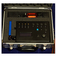
Back in part 1 I presented a photograph of the box that I’d found to hold the project. Here it is again.
We’re going to make some pretty heavy modifications to this box before we can use it so let’s get started. You’re going to need a drill with a set of HSS bits. Manual drills are better because they’re easier to control but you should be OK with a power drill. You’ll also need a set of small files and possibly a dremel or similar rotary tool.
Parts list
| Part | Quantity |
|---|---|
| approx 220 x 151 x 96mm box | 1 |
| 2.5mm stereo jack socket | 4 |
| 3mm green LED | 9 |
| 3mm amber LED | 4 |
| 3mm red LED | 1 |
| LED panel bezel | 14 |
| 4-pin mini-DIN socket | 5 |
| blue LED SPST locking button | 1 |
| Sparkfun analog thumb joystick | 1 |
| Sparkfun joystick breakout board | 1 |
| JHD204A 20×4 blue LCD | 1 |
| 20×4 LCD bezel | 1 |
| 2.1mm power connector | 1 |
| USB A socket | 1 |
| mini DPDT slide switch | 1 |
| SPST momentary button | 1 |
| Superglue (cyanoacrylate) | a tube |
The power socket
Mark an entry point on the short side of the case for the power connector, DPDT miniature switch and USB port. The USB port is an awkward shape. I drew a template around the USB port with a pencil before drilling a few small holes within the templated area and then connected the holes with a small file.
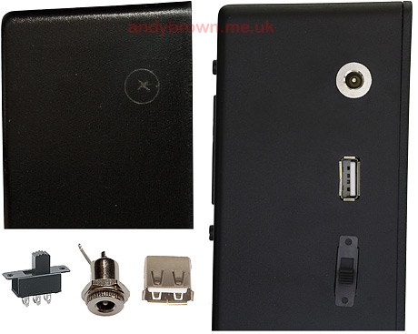
This is a good place to get used to the cutting and filing because this side will be hidden when the box is located inside its case so it doesn’t matter if you’re off a bit with alignment. As you can see the cutout I made for the DPDT switch is not level.
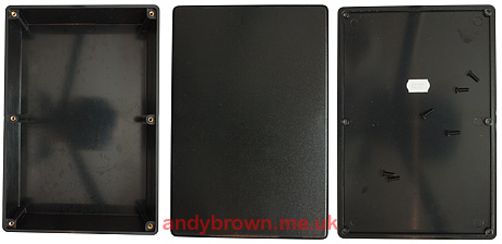
Cut out the front panel
Here’s the fun part. This will take several hours, more if you take your time to get it right. Perfectly round holes are not required because all the components are chosen to have ‘panel mount’ overlaps that will cover an uneven hole. However it is important that the holes line up, are evenly spaced where required and should be straight.
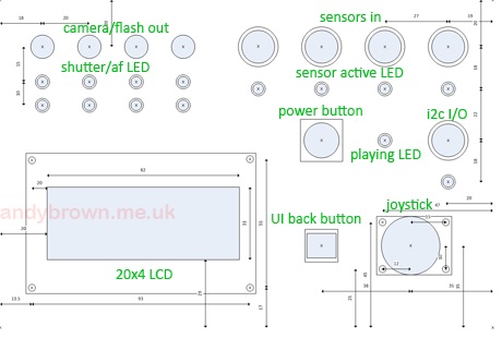
The plan above shows how the holes and the large LCD cutout are positioned against the box panel. I chose to use a printout of the plan as a guide for measuring and marking with a pencil. With hindsight it may have saved some time to just use the printout as a template and marked the center points of each hole with a sharp point through the template.
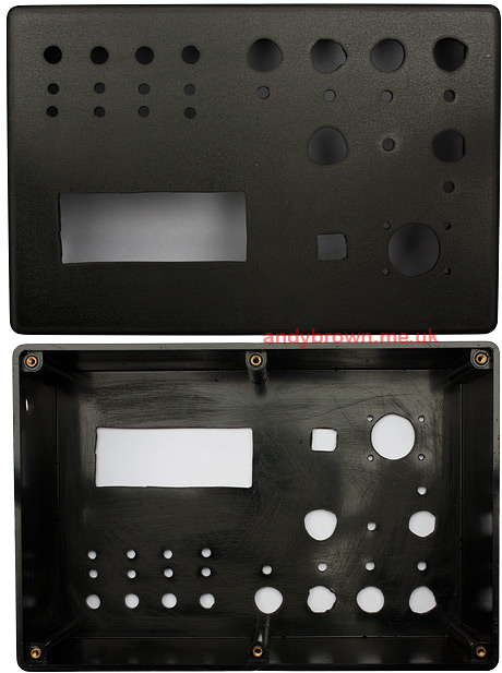
Many hours and much cursing later we have a result. It may look like a dogs breakfast at the moment but after the components are in none of the rough edges will be visible. I have a few tips for the cutting:
- Cut a small guide hole with your smallest drill bit before moving on to the bit that will cut the size of hole you want.
- Where a hole is larger than your largest bit, open it out gently with a hand-held round file going around in circular motions until you get there.
- Where a hole is very much larger than your drill (the LCD, the joystick) – cut many smaller holes around the edge of the proposed void and join them up using a dremel cutter on a very low speed.
- As you get close to the desired size of the component, keep pausing and trying to fit it. As soon as it will firmly press into place – stop.
- Use the dremel sparingly and slowly – it will easily melt the ABS plastic and clog up your bit.
When I was finished I sanded down the front panel with very fine wet-and-dry paper before spraying with a matte black finish.
Preparing the LEDs
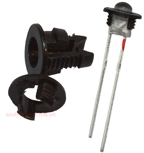
The 3mm LED holders that I bought turned out to be designed for thinner panels than my box. Rather than cast them aside and try to find others I decided to modify them to work. Here’s how.
- The original holder is shown at the top. The two long legs are supposed to snap into place below the LED. The two short legs are supposed to do the same for the panel.
- Cut off the panel legs entirely and cut down the other legs to about 2mm. It should look like the lower holder in the picture.
- Carefully apply a drop of superglue to the bottom half of the LED and spread it all around the circumference.
- Fit the holder over the LED and allow the glue to set.
Note how I have marked the long positive leg of the LED with a red marker. This is so I can easily recognise it after the legs have been trimmed.
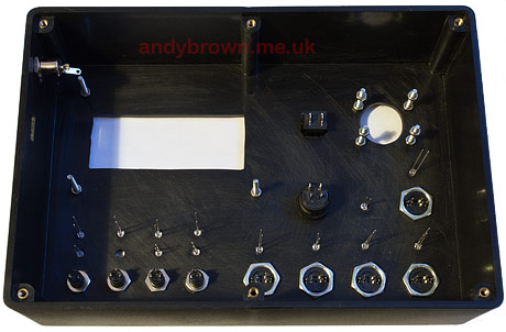
Fitting the components into the box
Firstly I fitted the LEDs and connectors to the front panel as shown in the this picture. With hindsight it would have been a better plan to solder the connecting wires to the sensor DIN plugs first because it was very fiddly to reach in there with a soldering iron later on.
All of the components in the box need power and ground connections so it makes sense to run power rails around the outer edge of the box so that the components can tap in to power without creating too much of a rats nest of wiring.
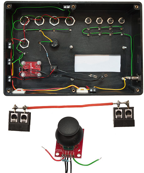
The above photograph shows how I used a set of 2-way PCB wiring terminals to create the wiring bus. These terminals were superglued to the sides of the box and I used some stick-on cable-tie bases as wiring guides so that the wires ran flush to the edges of the case.
The photograph also shows the playstation joystick fixed to the Sparkfun breakout board and mounted in the case with some long screws, some nuts and plastic washers.
All together now
Here it is, all wired up and ready to close the box. You can just about make out the Arduino Mega at the back behind the stripboard and the piezo buzzer. It’s not pretty, and it took me a few weekend afternoon’s to wire it up, but it works perfectly.
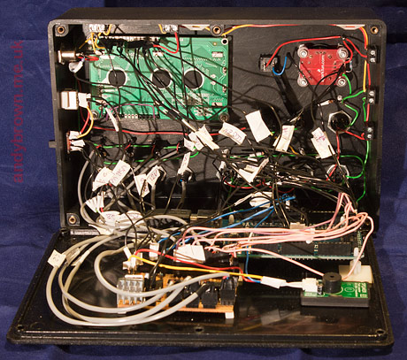
All the wires are labelled with a white tag so that I know where they’re supposed to go. The stripboard circuit and the piezo buzzer are superglued to the base. The Arduino Mega is mounted on plastic PCB standoffs that have their own self-adhesive base.
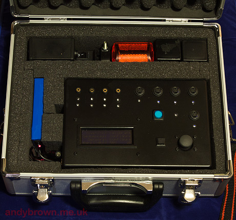
Finally, here it is in the aluminium flight case. The battery is mounted vertically to the left and there is space at the top for an array of sensors and accessories. In this photograph I’m carrying an IR beam emitter/receiver, lightning sensor, sonic sensor plus camera and sensor leads. Everything I’d need for a day out.
Article series index
Use the following links to navigate through this series of articles.
| Part 1: Design | |
| Part 2: The control unit electronics | |
| Part 3: Control unit assembly | You are here. |
| Part 4: The operating system | Coming soon! |
| Part 5: The infra-red beam sensor | |
| Part 6: The X-band radar sensor | Coming soon! |
| Part 7: The PIR infra-red sensor | Coming soon! |
| Part 8: The lightning trigger | Coming soon! |
| Part 9: The ultrasonic trigger | Coming soon! |
| Part 10: The sonic trigger | Coming soon! |
| Part 11: The laser trigger | Coming soon! |